42
CAREFULLY CONSULT THE INSTRUCTION AND MANUTENTION BOOKLET
BEFORE UNPLUG THE NEGATIVE POLE OF THE VEICHLE.
ATTENTION TO THE DISPOSITIVES OF AIR BAG AND CAR RADIO
CODICATED.
WARNINGS FOR INSTALLATION
!
ELECTRICAL CONNECTIONS
Dont strech or shortn the antenna wire, the shielded cables of ultrasound sensor and of
elettronic socket .
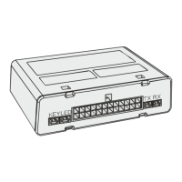
The ELECTRONIC SOCKET/LED BUTTON must be fixed in a easy position
accessible and visible both inside and outside of the vehicle. For fix the ELECTRONIC
SOCKET/LED to the dashboard execute a hole with a diameter of 10mm
All eletrical connection must be done reliable and secure (by welding the junctions).
The isolament of junctions must be realized with material quality (electrical tape) to be
sure not provacate a short circuit.
• RED WIRE : connect to the positive of fuse service ,interposing a fuse
• ground of the alarm, connect to the ground of vehicle.BLACK WIRE:
• YELLOW WIRE e YELLOW/RED: Factory default settings: Connect one of the two wire to right
direction indicator and the other one to the left direction indicator.
Other settings: Power outputs programmable via Personal Computer:
Provide a positive signal in the alarm phase of the device for a time equal to the siren sound
cycle: 25 seconds.
Provide a positive constant signal with alarm activeted. The Signal allow the abilition of an
electric power window module or the satellite alarm with positive command.
Provide a positive constant signal a vehicle in motion (ignition key +15). If the device read the
vehicle code in motion from BUS network data; the system will provide a positive signal on
that wire.
Provide a positive constant signal when the vehicle reverse gear is engaged. If the device
reads data of the reverse gear on the bus network, the system will be provide a positive
signal on the wire in the presence of reverse gear.
Provide a constant positive signal in motion (ignition key +15) up to speed of 15Km/h.If the
device reads the presence of the vehicle code in motion from the CanBus network, the
system will provide the positive signal on this wire only if the vehicle speed is under 15km/h
• PURPLE WIRE: connect to a positive ignition key. On that wire must be always present a positive
signal both in the ignition phase and with the engine running. (This signal can be detected from
CANBUS see file ISAUTO vehicle functionality)
• RED/GREY WIRE CAN HIGH and RED/BROWN CAN-LOW: data input wire of the CanBus
type vehicle network (The system can protocol via network the arm data and disarm data, depend of
the model of vehicle)
Set the code of the vehicle with button of control unit or via P.C
• YELLOW/GREY WIRE: Programmable input via PC
It is automatically selected like input data LIN BUS of the network of the vehicle (The system can
protocol via network the arm data and disarm data, depend of the model of vehicle)
Otherwise the input is set as a factory on command auxiliary alarm input
in this case it is also possible to enable all the options allowed for the alarm input wires see
description of the input wires, doors, hood and trunk.
 Loading...