The components must be off-circuit.
!
To avoid incorrect results the measuring points must be free of dirt, oil, solder lacquer or similar.
!
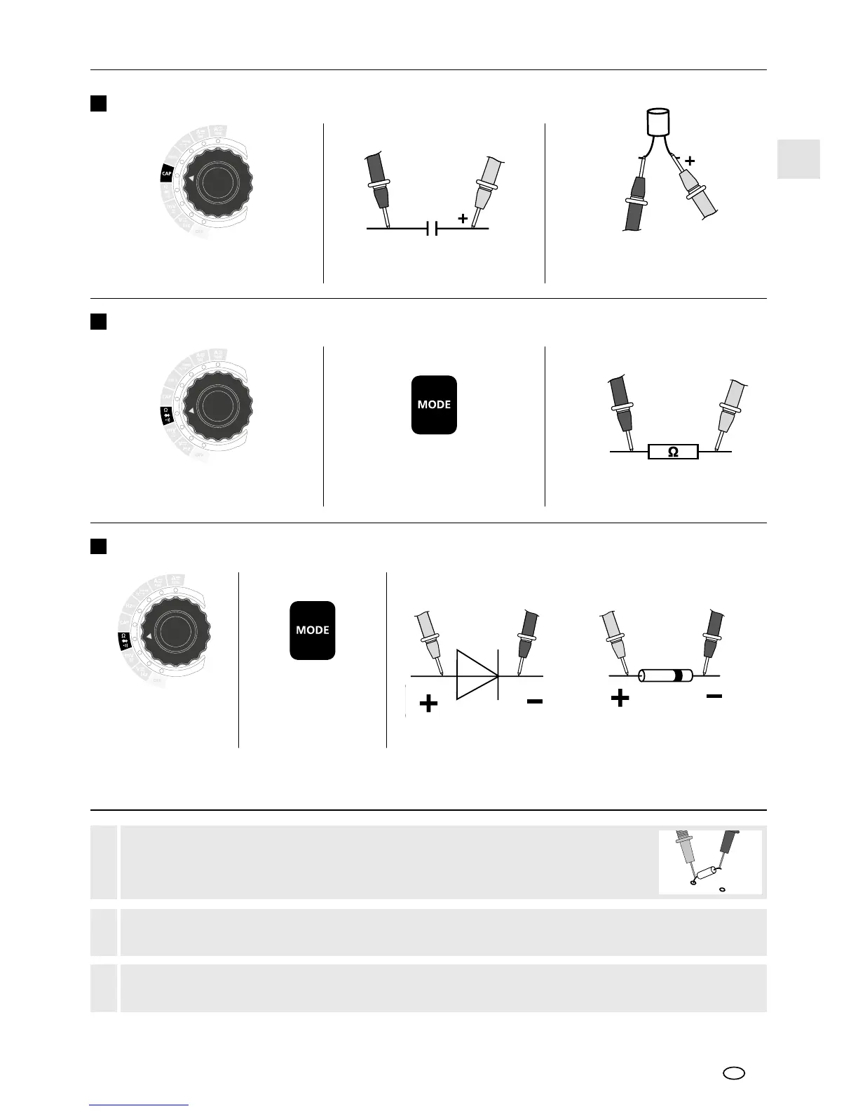
Components (7: Resistors, 8: Capacitors, 9: Diodes) can only be measured
correctly in isolation. It may therefore be necessary to disconnect the components
from the rest of the circuit.
!
Ω , diode check
and continuity
check selection
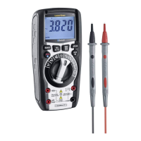
Connect the measuring contacts
to the object to be tested
Ω , diode check and
continuity check selection
Connect the measuring contacts
to the object to be tested
If "O.L." appears on the display instead of a measured value, the diode has either been tested in the
reverse direction or is faulty. If 0.0 V is measured, the diode is faulty or a short-circuit has occurred.
Forward direction
BlackBlack RedRed
Diode test
Diode test
RedBlack
Resistance measurement
In the case of poled capacitors,
connect the positive pole
to the red test prod
RedBlack
Capacitance measurement
Capacitance measurement
21
EN
 Loading...