LAUNCH TireChangerTWC-581
14
Directional Switch’s Installation (Service Only)
1
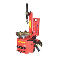
Connecting the wire harness to the switch (fig31)
Observe the identification tags on wires and match then to the poles on the switch such as U2 to U2
They is no
sequence, but make sure the wires and poles match
Fig.31
2
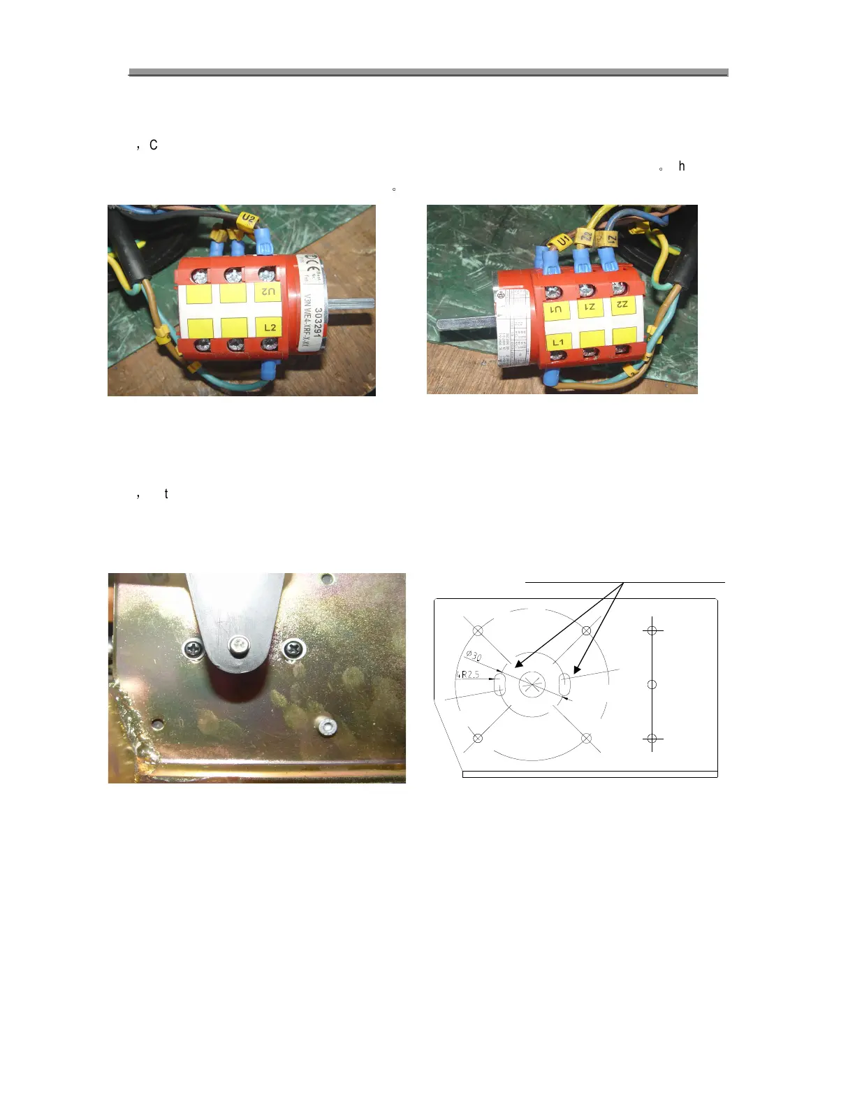
Installation of the switch
The switch’s position to the bracket is shown as in fig32, you may have to rotate the switch slightly in the slots with
the attachment screw slightly loose to position the switch so that clockwise and counter clock potation of the motor
occurs correctly. Once in the correct position tighten the two screws.
Adjustmentslotsforswitchlocation
The switch parameter
Fig32
 Loading...