5
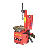
Fig.01-2
The supplementary arm is shown in Fig. 01-2.
a. Back swivel arm
b. Hexagonal slide bar
c. Forward swivel arm
d. Follower Arm Assembly (a&c)
e. Post assembly
f. Lifting cylinder
g. Up Down control lever
h. Control box
i. Press block
j. Lifting roller
k. Lock bar
m. Spacer pin control
n. Spacer pin
Accessories provided are shown in Fig.02
001-Tire lever
002-Brush
Fig.02-a
Fig.02-b
Tools
To ensure the smooth installation and adjustment,
please prepare the following tools: Two adjustable
wrenches, one set of metric box wrenches, one pair of
pliers, one screwdriver, and one digital multi-meter (for
voltage measurement).
Installation
Unpacking
Unpack according to the instructions on the
package. Remove the packing materials and
inspect the machine for possible damage or
loss of accessories during shipment.
Keep the packing materials out of the reach of
children. Handle in an appropriate way if the
packing material is likely to cause pollution.
Remove the cabinet, column, swing arm and
accessory box attached to the bottom skid and
keep them in safe place
Caution:
A special anti-rust coating is applied on the some
parts and may attract dust. Clean it when
necessary.
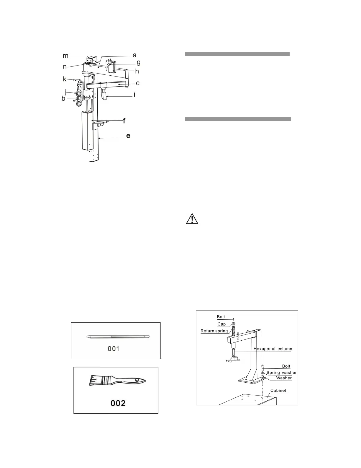
Installation
Install the return spring and cap on the
Hexagonal bar. Mount the column to the base
cabinet as show in Fig.02, and then torque
down all fastens.(All hardware is provided and
can be found in the accessory box)
Fig.03
 Loading...