LAUNCH TireChangerTWC-581
Fig.09
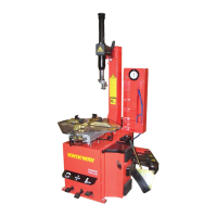
Install the lifting roller assemblies as is shown in
Fig.09.
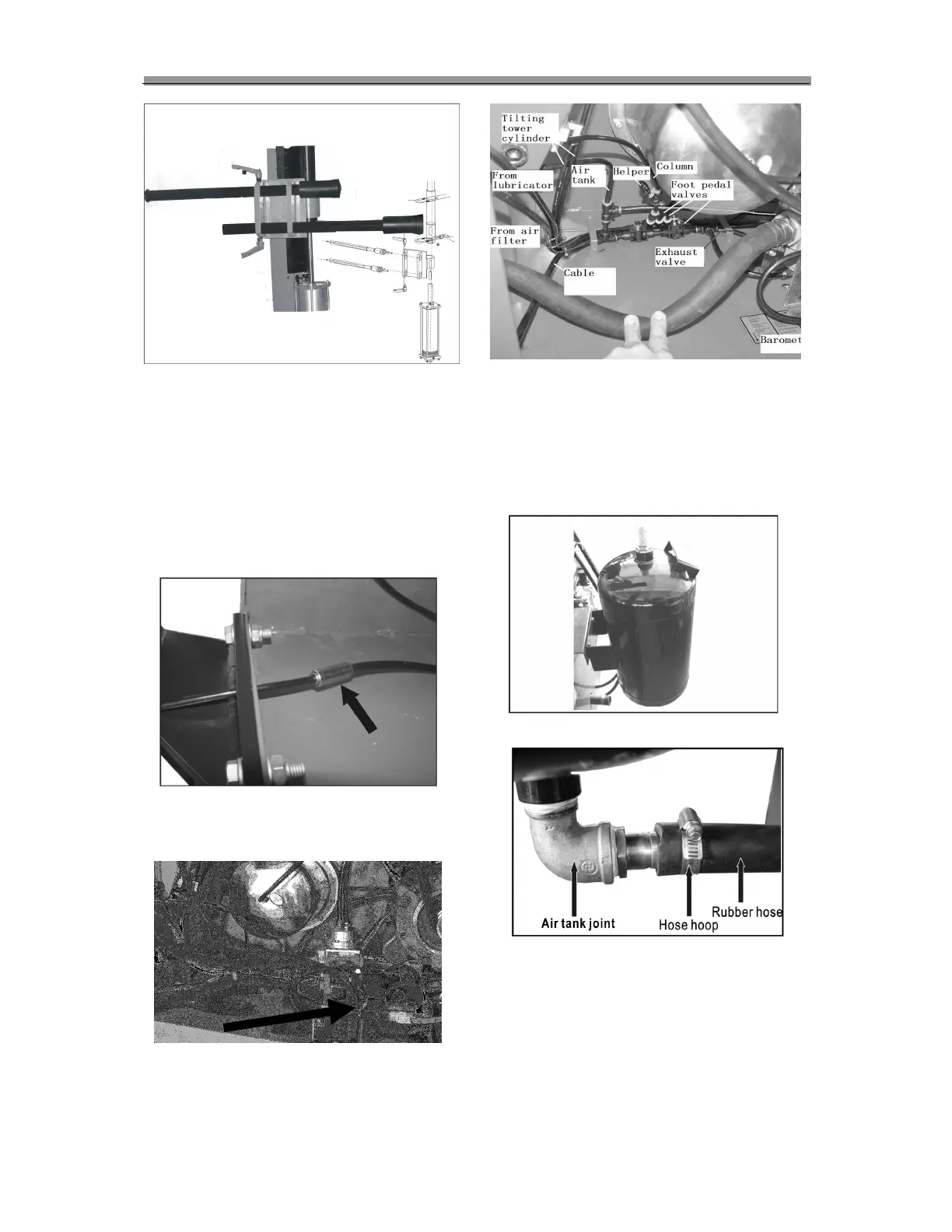
Air Connections
Find air out from the post and assist arm and
insert them into the inline quick disconnect
respectively. (Fig.10)
Fig.10
Take out rubber hose and connect it to the #1
valve Fig.11, feed the other end of hose out
cabinet through the hole on rear panel.
Fig.11
Installation of Air Tank
Fix the air tank on the cabinet with two sets of
bolts, nuts, spring washers and flat washer (Fig.
12).
Connect the rubber hose with the joint on the air
tank and fasten the screw of the hose hoop as
figure 13.
Fig.12
Fig.13
Mount the side plate of cabinet to its original
position.
 Loading...