24
4. Control panel
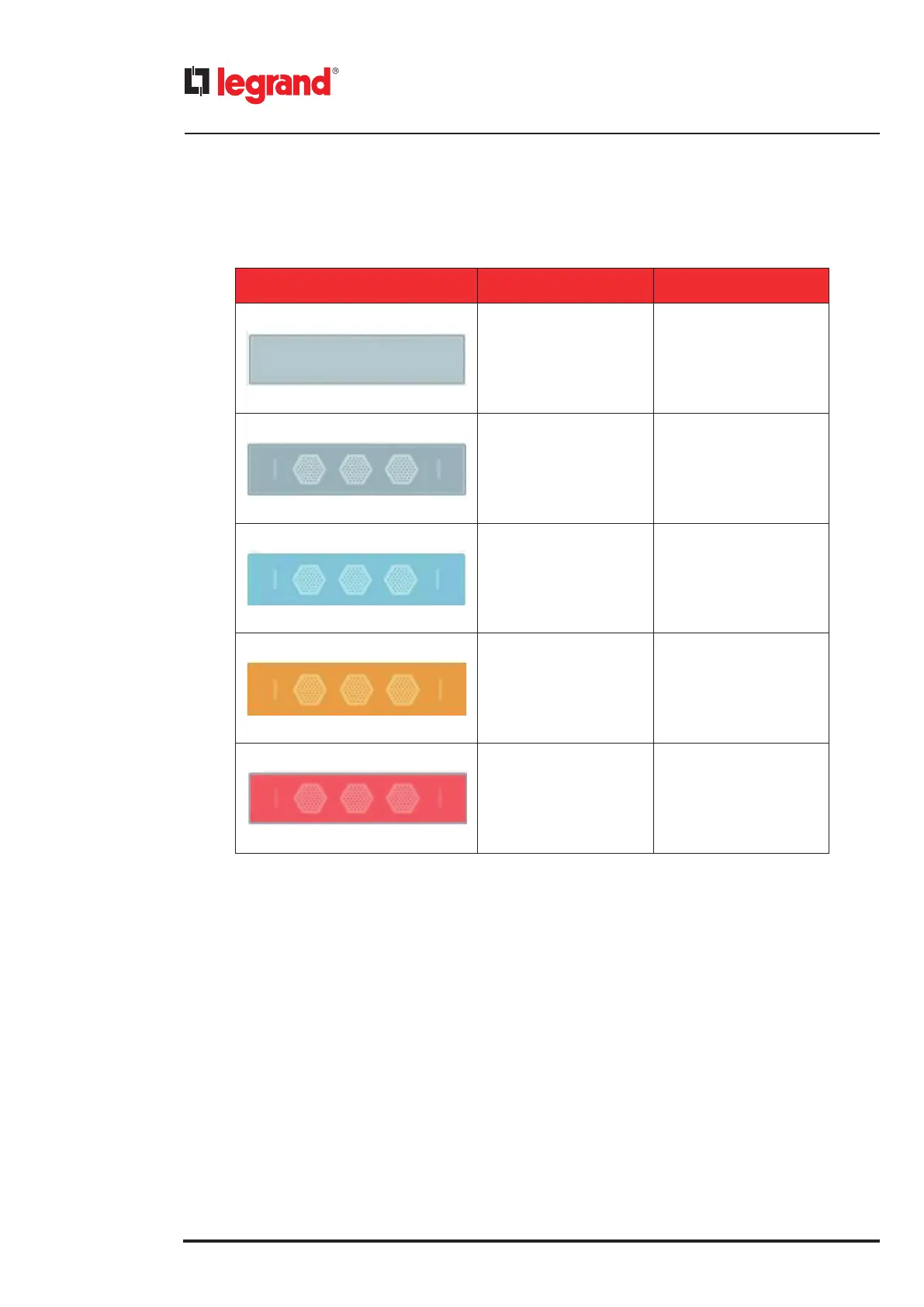
The icons regarding the power modules are the following ones:
PM ICON COLOR DESCRIPTION
Roundish rectangular
with a pale grey filling
PM absent
Roundish rectangular
with three fan icons inside
PM present
Roundish rectangular
with a pale blue filling
PM in stand-by
Roundish rectangular
with a pale yellow filling
Warning s related
to the PM
Roundish rectangular
with a pale red filling
PM with alarms
4.3 Status bar
The Status Bar is a graphical line that describes the actual status of the UPS.
It can assume different states and sizes:
• Green and thin lane: normal situation (no alarm neither warning)
• Yellow and thin lane with text: warning is occurring. The text explains the warning.
• Red and bigger lane with text: alarm is occurring. The text explains the alarm.
 Loading...