3
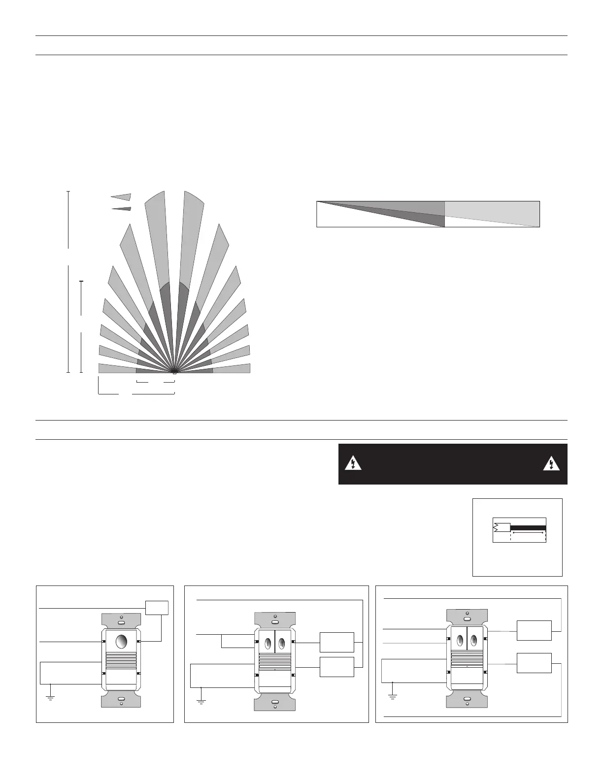
COVERAGE PATTERNS
Coverage testing has been performed according to the NEMA WD 7 guideline. For best performance, use in spaces not larger than 15’ x
12’.
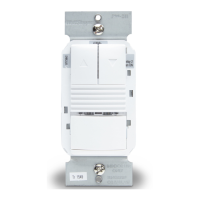
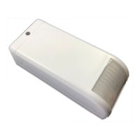
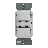
PIR Sensor
The sensor has a two-tiered, multi-cell viewing Fresnel lens with 180 degree field of view. The red LED on the sensor flashes when the
PIR detects motion.
Masking the Lens
Opaque adhesive tape is supplied so that sections of the PIR sensor’s view can be masked. This allows you to eliminate coverage
in unwanted areas. Since masking removes bands of coverage, remember to take this into account when troubleshooting coverage
problems.
PIR
Coverage
7.5’
(2.2m)
15’
(4.5m)
20’
(6.1m)
35’
Major motion
Minor motion
Top View
4’
(1.2m)
20’
(6.1m)
35’
(10.6m)
0
Side View
INSTALLATION
1. \Make sure that the power has been turned OFF at the circuit breaker.
2. Connect wires to the PW flying leads as shown in the wiring diagram
that is appropriate to the PW model and electrical supply. The 2
ground wires (green and green/yellow) must be fastened to
ground for the sensor to work properly.
3. Attach the sensor to the wall box by inserting screws into the two wide holes on the top and bottom of
the attached metal bracket. Match them up with the holes in the wall box and tighten.
4. Turn the circuit breaker ON. Wait one minute, then push the Auto ON/OFF switch for each load and
the lights will turn ON. There is a delay due to initial power-up of the sensor that only occurs during
installation.
5. Test and adjust the sensor if necessary.
6. Install industry standard decorator.
#12 – #14 AWG
Cu Wire Only
1/2"
WARNING: TURN THE POWER OFF AT THE
CIRCUIT BREAKER BEFORE WIRING.
Load
Red
Line Black
Neutral
Ground
Green
Ground
Green/Yellow
PW-100 and PW-100-347 Wiring
Blue
Primary
Load
Secondary
Load
Neutral
Red
Brown
Line 2
Line 1 Black
Neutral
Ground
Ground
Green/Yellow
Green
PW-200 and PW-200-347 Dual Circuit WiringPW-200 and PW-200-347 Bi-Level Wiring
Neutral
Blue
Line Black
Secondary
Load
Brown
Primary
Load
Red
Ground
Ground
Green/Yellow
Green
 Loading...