Page 12
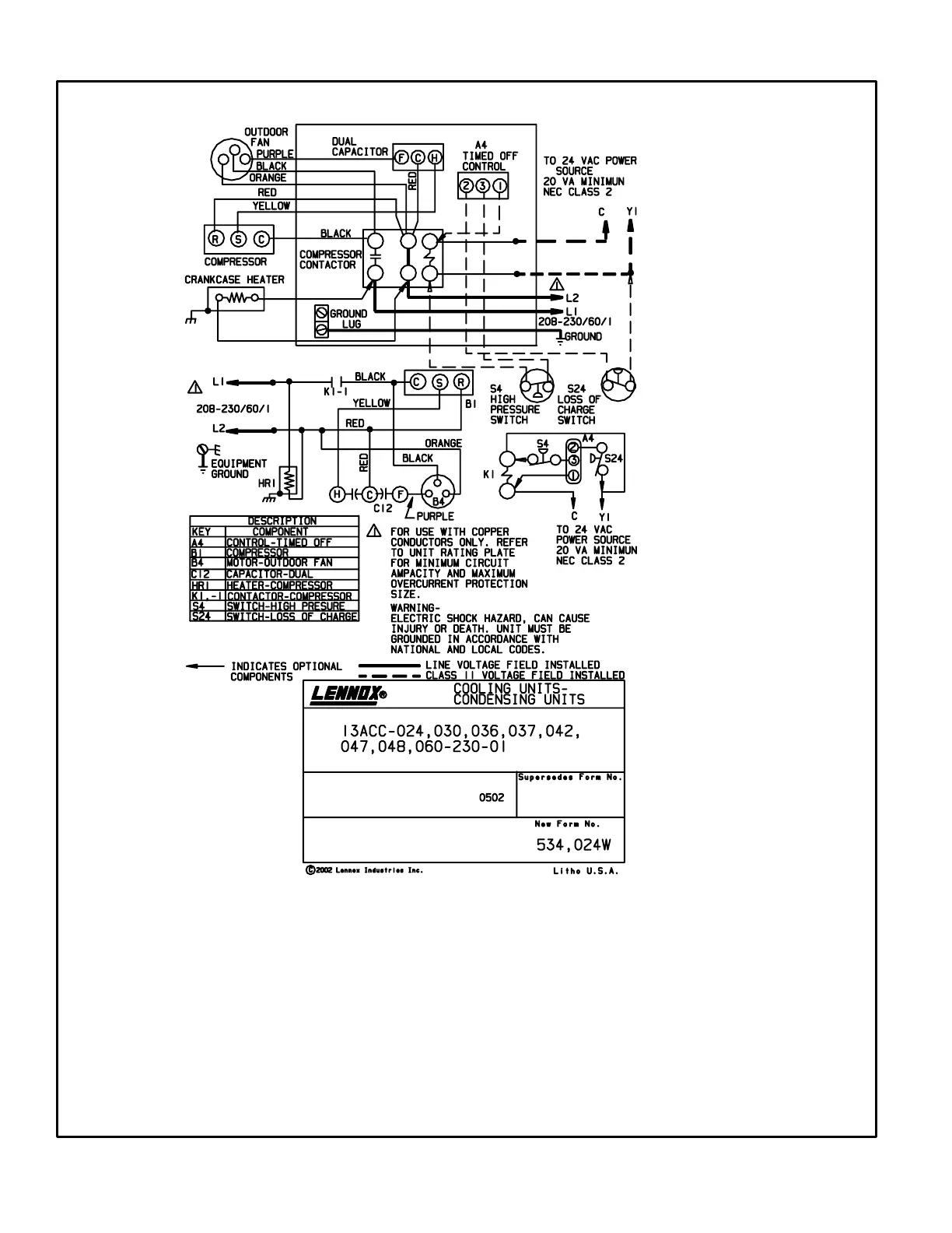
V − WIRING DIAGRAMS AND SEQUENCE OF OPERATION
13ACC 2 THROUGH 5 TON OPERATING SEQUENCE
NOTE− The thermostat used may be electromechanical or electronic.
NOTE− Transformer in indoor unit supplies power (24 VAC) to the thermostat and outdoor unit controls.
COOLING:
1− Cooling demand initiates at Y1 in the thermostat.
2− 24VAC from indoor unit (Y1) energizes the timed off control TOC (if used), which energizes compressor contactor
K1 provided the 5 minute delay is satisfied.
3− K11 N.O. closes, energizing compressor (B1) and outdoor fan motor (B4).
4 − Compressor (B1) and outdoor fan motor (B4) begin immediate operation..
END OF COOLING DEMAND:
5− Cooling demand is satisfied. Terminal Y1 is deenergized.
6− Compressor contactor K1 is deenergized.
7− K11 opens and compressor (B1) and outdoor fan motor (B4) are deenergized and stop immediately.

 Loading...