Page 9
Expansion Valve Systems
Charging Using the Approach Method
TXV Systems − Outdoor Temp. >
65_F (18_C)
IMPORTANT
The following procedure requires accurate read
ings of ambient (outdoor) temperature, liquid
temperature and liquid pressure for proper
charging. Use a thermometer with accuracy of +
2
°F (+
1.1°C) and a pressure gauge with accuracy
of +
5 PSIG ( +34.5 kPa).
When an expansion valve system is being charged when
the outdoor ambient temperature is 65_F (16_C) or above,
it is best to charge the unit using the approach method.
Subtract the outdoor ambient temperature from the liquid
line temperature to determine the Approach temperature.
(Liquid Line _F (_C) − Outdoor Ambient _F (_C) = Ap
proach Temperature.) The resulting difference (Approach
temperature) should agree with the values given in table 3.
If not, add refrigerant to lower the approach temperature or
recover refrigerant from the system to increase the ap
proach temperature.
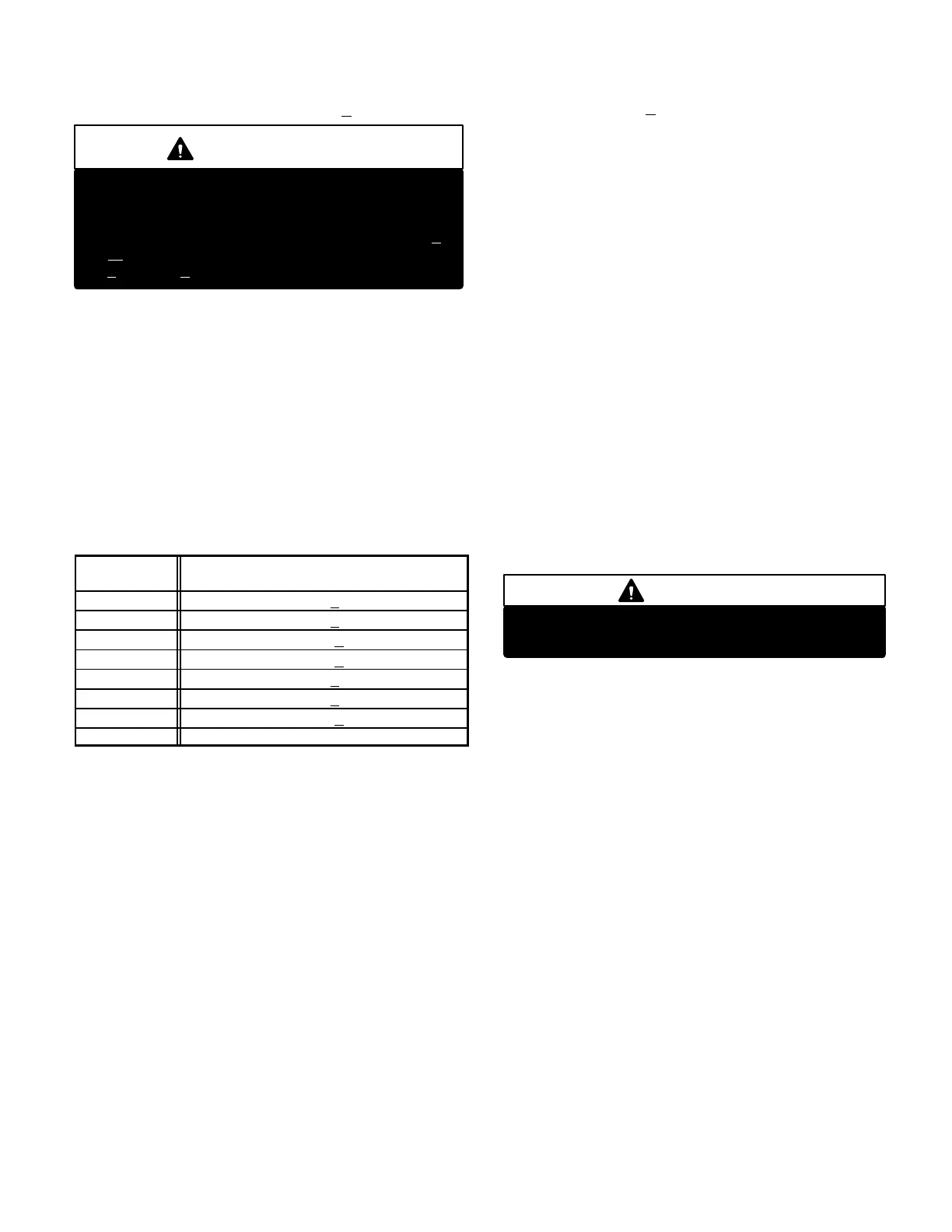
Table 3
Approach Temperatures
(TXV Systems Only)
Model No.
Approach Temperature
Liquid Line − Outdoor Ambient _F (_C)
13ACC−024 9 (5) + 1
13ACC−030 6 (3) + 1
13ACC−036 10 (6) + 1
13ACC−037 12 (7) + 1
13ACC−042 8 (4) + 1
13ACC−048 7 (4) + 1
13ACC−047 10 (6) + 1
13ACC−060 12 (7) + 1
NOTE − For best results, use the same digital thermometer to check
both outdoor ambient and liquid temperatures.
Charging Using the Subcooling Method
TXV & Fixed Orifice Systems Outdoor Temp.
>
65_F (18_C)
If you charge a fixed orifice system when the outdoor ambi
ent is 65_F (18_C) or above, use the subcooling method to
charge the unit.
1 − With the manifold gauge hose still on the liquid service
port and the unit operating stably, use a digital ther
mometer to record the liquid line temperature.
2 − At the same time, record the liquid line pressure reading.
3 − Use a temperature/pressure chart for HCFC22 to de
termine the saturation temperature for the liquid line
pressure reading.
4 − Subtract the liquid line temperature from the saturation
temperature (according to the chart) to determine sub
cooling. (Saturation temperature − Liquid line tem
perature = Subcooling)
5 − Compare the subcooling value with those in table 4. If
subcooling is greater than shown, some refrigerant
must be recovered. If subcooling is less than shown,
some refrigerant must be added.
E − Oil Charge
Refer to compressor nameplate.
IV − MAINTENANCE
Make sure all power is disconnected before
beginning electrical service procedures.
DANGER
At the beginning of each cooling season, the system should be
cleaned as follows:
A − Outdoor Unit
1 − Clean and inspect condenser coil. (Coil may be
flushed with a water hose).
2 − Visually inspect all connecting lines, joints and coils for
evidence of oil leaks.
NOTEOutdoor fan motors are permanently
lubricated.
B − Indoor Coil
1 − Clean coil if necessary.
2 − Check connecting lines and coil for evidence of oil
leaks.
3 − Check condensate line and clean if necessary.
C − Indoor Unit
1 − Clean or change filters.
2 − Bearings are prelubricated and need no further oiling.
3 − Check all wiring for loose connections.
4 − Check for correct voltage at unit.
5 − Check amp−draw on blower motor.
Unit nameplate_________Actual_________.

 Loading...