Page 7
B − Service Valves
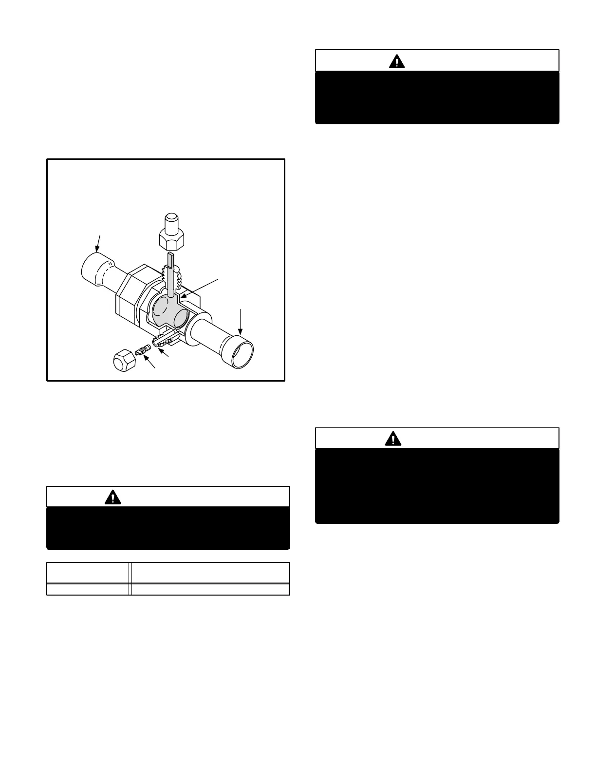
Suction Line (Ball Type) Service Valve
A balltype full service valve is used on all 13ACC units.
Valves are not rebuildable. If a valve has failed it must be re
placed. A ball valve is illustrated in figure 10.
The ball valve is equipped with a service port. A schrader valve
is factory installed. A service port cap is supplied to protect the
schrader valve from contamination and assure a leak free
seal.
SUCTION LINE (BALL TYPE) SERVICE VALVE
(VALVE OPEN)
FIGURE 10
SCHRADER CORE
SERVICE PORT
SERVICE
PORT
CAP
STEM CAP
INLET
(FROM INDOOR COIL)
OUTLET
(TO COMPRESSOR)
STEM
USE ADJUSTABLE WRENCH
ROTATE STEM CLOCKWISE 90_ TO CLOSE
ROTATE STEM COUNTERCLOCKWISE 90_ TO OPEN
BALL
(SHOWN OPEN)
III − CHARGING
The unit is factory−charged with the amount of R−22 refrig
erant indicated on the unit rating plate. This charge is
based on a matching indoor coil and outdoor coil with a 20
foot (6.1 m) line set. For varying lengths of line set, refer to
table 2for refrigerant charge adjustment. A blank space is pro
vided on the unit rating plate to list actual field charge.
IMPORTANT
If line length is greater than 20 feet (6.1 m) add this
amount. If line length is less than 20 feet (6.1 m),
subtract this amount.
LIQUID LINE
3/8 in. (10 mm)
TABLE 2
Ounce per 5 foot (ml per mm) adjust
from 20 foot (6.1m) line set*
*If line set is greater than 20 ft. (6.1m) add this amount. If line set
is less than 20 feet (6.1 m) subtract this amount
SET DIAMETER
3 ounce per 5 feet (90 ml per 1524 mm)
Units are designed for line sets up to 50 feet (15.2 m).
Consult Lennox Refrigerant Piping Manual for line sets
over 50 feet (15.2 m).
A − Pumping Down System
CAUTION
Deep vacuum operation (operating compressor at 0
psig or lower) can cause internal fusite arcing
resulting in a damaged or failed compressor. This
type of damage will result in denial of warranty claim.
The system may be pumped down when leak checking the
line set and indoor coil or making repairs to the line set or
indoor coil.
1− Attach gauge manifold.
2− Front seat (close) liquid line valve.
3− Start outdoor unit.
4− Monitor suction gauge. Stop unit when 0 psig is reached.
5− Front seat (close) suction line valve.
B − Leak Testing (To Be Done
Before Evacuating)
1− Attach gauge manifold and connect a drum of dry nitro
gen to center port of gauge manifold.
2− Open high pressure valve on gauge manifold and
pressurize line set and indoor coil to 150 psig (1034
kPa).
3− Check lines and connections for leaks.
NOTE−The preferred method is to use an electronic leak or
Halide detector. Add a small amount of R22 (3 to 5 psig
[20kPa to 34kPa]) then pressurize with nitrogen to 150 psig.
4− Release nitrogen pressure from the system, correct any
leaks and recheck.
CAUTION
When using dry nitrogen, a pressure reducing reg
ulator must be used to prevent excessive pres
sure in gauge manifold, connecting hoses, and
within the system. Regulator setting must not ex
ceed 150 psig (1034 kpa). Failure to use a regulator
can cause equipment failure resulting in injury.

 Loading...