Page 3
Torque requirements
Part Recommended Torque
Service Valve Cap 8 ft. − lb 11 NM
Sheet metal screws 16 in. − lb. 2 NM
Machine screws #10 28 in. − lb. 3 NM
Compressor bolts 90 in. − lb. 10 NM
Gauge port seal cap 8 ft. − lb. 11 NM
ELECTRICAL DATA
General
Data
Model No.
13ACC−024
−230
13ACC−030
−230
13ACC−036
−230
13ACC−037
−230
13ACC−042
−230
13ACC−047
−230
13ACC−048
−230
13ACC−060
−230
Line voltage data − 60 hz
208/230v −
1ph
208/230v −
1ph
208/230v −
1ph
208/230v −
1ph
208/230v −
1ph
208/230v −
1ph
208/230v −
1ph
208/230v −
1ph
Rec. Max. fuse size (amps) 20 30 35 30 35 40 50 60
Minimum circuit ampacity 14.0 18.0 20.4 19.5 22.5 24.6 31.5 38.0
Compressor
Rated load amps 10.3 13.5 15.4 14.7 16.5 18.3 23.7 28.9
Power factor .96 .96 .96 .98 .98 .94 .96 .96
Locked rotor amps 56.0 72.5 88.0 83.0 95.0 109.0 129.0 169.0
Outdoor Coil
Full load amps 1.1 1.1 1.1 1.1 1.9 1.7 1.9 1.9
Fan Motor
Locked rotor amps 1.9 1.9 1.9 1.9 4.1 3.1 4.1 4.1
*Refer to National or Canadian Electrical Code manual to determine wire, fuse and disconnect size requirements.
NOTE Extremes of operating range are plus 10% and minus 5% of line voltage.
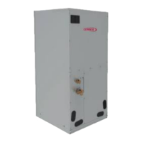
I − UNIT COMPONENTS
COMPRESSOR
CONTROL
BOX
SUCTION LINE
SERVICE VALVE
DISCHARGE LINE
OUTDOOR
FAN/MOTOR
13ACC UNIT COMPONENTS
FIGURE 1
LIQUID LINE
SERVICE VALVE
SUCTION
LINE
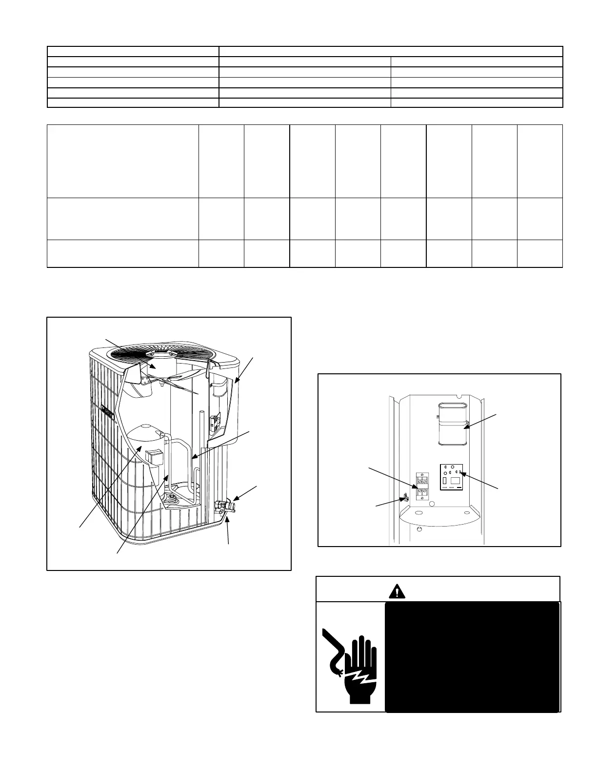
A − Control Box (Figure 2)
13ACC units are not equipped with a 24V transformer. All
24 VAC controls are powered by the indoor unit. Refer to
wiring diagram.
Electrical openings are provided under the control box cov
er. Field thermostat wiring is made to colorcoded pigtail
connections.
1 − Compressor Contactor K1
The compressor is energized by a contactor located in the
control box. See figure 2. Single−pole contactors are used
in 13ACC series units. K1 is energized by the indoor ther
mostat terminal Y1 (24V) when thermostat demand is
present.
FIGURE 2
DUAL CAPACITOR
(C12)
TIMED OFF
CONTROL. (TOC)
(OPTION)
COMPRESSOR
CONTACTOR
(K1)
13ACC UNIT CONTROL BOX
GROUNDING
LUG
DANGER
13ACC units use singlepole con
tactors. One leg of compressor,
capacitor and condenser fan are
connected to line voltage at all
times. Potential exists for electri
cal shock resulting in injury or
death. Remove all power at dis
connect before servicing.
Can cause personal injury or death.

 Loading...