Page 4
2 − Dual Capacitor C12
The compressor and fan in 13ACC series units use per
manent split capacitor motors. The capacitor is located
inside the unit control box (see figure 2). A single dual"
capacitor (C12) is used for both the fan motor and the
compressor (see unit wiring diagram). The fan side and
the compressor side of the capacitor have different MFD
ratings. Ratings will be on compressor nameplate and
condenser fan nameplate.
3 − Timed Off Control TOC (option)
The time delay is electrically connected between thermo
stat terminal Y and the compressor contactor. Between
cycles, the compressor contactor is delayed for 5 minutes ±
2 minutes but may last as long as 8 minutes. At the end of
the delay, the compressor is allowed to energize. When
thermostat demand is satisfied, the time delay opens the
circuit to the compressor contactor coil and the compressor
is de−energized.
Without the time delay it would be possible to short cycle
the compressor. A scroll compressor, when short cycled,
can run backward if head pressure is still high. It does not
harm a scroll compressor to run backward, but it could
cause a nuisance tripout of safety limits (internal overload).
For this reason, if a TOC delay should fail, it must be re
placed. Do not bypass the control.
B − Compressor
FIGURE 3
SCROLL COMPRESSOR
DISCHARGE
SUCTION
All 13ACC units utilize a scroll compressor. The scroll com
pressor design is simple, efficient and requires few moving
parts. A cutaway diagram of the scroll compressor is shown in
figure 3. The scrolls are located in the top of the compressor
can and the motor is located just below. The oil level is immedi
ately below the motor.
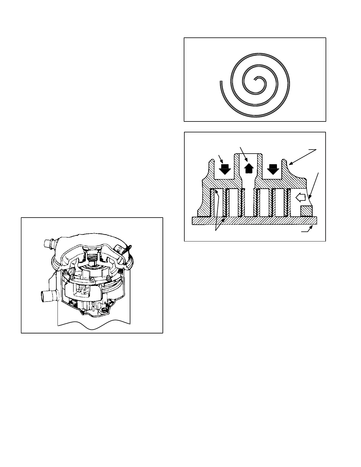
The scroll is a simple compression concept centered around
the unique spiral shape of the scroll and its inherent properties.
Figure 4 shows the basic scroll form. Two identical scrolls are
mated together forming concentric spiral shapes (figure 5).
One scroll remains stationary, while the other is allowed to "or
bit" (figure 6). Note that the orbiting scroll does not rotate or
turn but merely orbits the stationary scroll.
NOTE − During operation, the head of a scroll compressor may
be hot since it is in constant contact with discharge gas.
FIGURE 4
SCROLL FORM
FIGURE 5
STATIONARY SCROLL
ORBITING SCROLL
DISCHARGE
SUCTION
CROSS−SECTION OF SCROLLS
TIPS SEALED BY
DISCHARGE PRESSURE
DISCHARGE
PRESSURE
The counterclockwise orbiting scroll draws gas into the outer
crescent shaped gas pocket created by the two scrolls (figure
6 − 1). The centrifugal action of the orbiting scroll seals off the
flanks of the scrolls (figure 6 − 2). As the orbiting motion contin
ues, the gas is forced toward the center of the scroll and the
gas pocket becomes compressed (figure 6 − 3). When the
compressed gas reaches the center, it is discharged vertically
into a chamber and discharge port in the top of the compressor
(figure 5). The discharge pressure forcing down on the top
scroll helps seal off the upper and lower edges (tips) of the
scrolls (figure 5). During a single orbit, several pockets of gas
are compressed simultaneously providing smooth continuous
compression.
The scroll compressor is tolerant to the effects of liquid return.
If liquid enters the scrolls, the orbiting scroll is allowed to sepa
rate from the stationary scroll. The liquid is worked toward the
center of the scroll and is discharged. If the compressor is re
placed, conventional Lennox cleanup practices must be used.

 Loading...