Page 6
Diagnostic LEDs
The defrost board uses two LEDs for diagnostics. The LEDs
flash a specific sequence according to the condition.
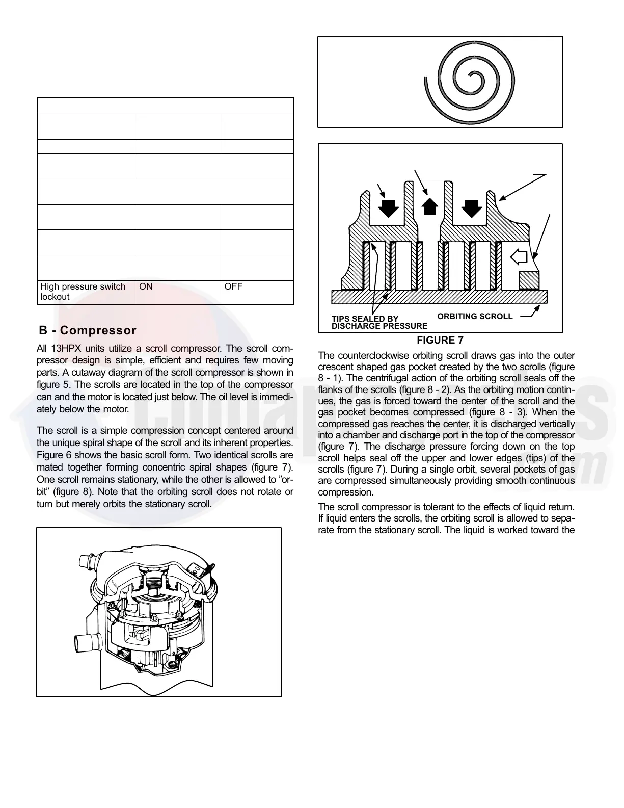
TABLE 1
Defrost Control Board Diagnostic LED
Mode Green LED (DS2)
Red LED
(DS1)
No power to control OFF OFF
Normal operation /
power to control
Simultaneous Slow FLASH
Anti-short cycle lock-
out (5 minute)
Alternating Slow FLASH
Low pressure switch
fault
OFF Slow FLASH
Low pressure switch
lockout
OFF ON
High pressure switch
fault
Slow FLASH OFF
High pressure switch
lockout
ON OFF
B − Compressor
All 13HPX units utilize a scroll compressor. The scroll com-
pressor design is simple, efficient and requires few moving
parts. A cutaway diagram of the scroll compressor is shown in
figure 5. The scrolls are located in the top of the compressor
can and the motor is located just below. The oil level is immedi-
ately below the motor.
The scroll is a simple compression concept centered around
the unique spiral shape of the scroll and its inherent properties.
Figure 6 shows the basic scroll form. Two identical scrolls are
mated together forming concentric spiral shapes (figure 7).
One scroll remains stationary, while the other is allowed to "or-
bit" (figure 8). Note that the orbiting scroll does not rotate or
turn but merely orbits the stationary scroll.
FIGURE 5
SCROLL COMPRESSOR
DISCHARGE
SUCTION
NOTE − During operation, the head of a scroll compressor may
be hot since it is in constant contact with discharge gas.
FIGURE 6
SCROLL FORM
FIGURE 7
STATIONARY SCROLL
ORBITING SCROLL
DISCHARGE
SUCTION
CROSS−SECTION OF SCROLLS
TIPS SEALED BY
DISCHARGE PRESSURE
DISCHARGE
PRESSURE
The counterclockwise orbiting scroll draws gas into the outer
crescent shaped gas pocket created by the two scrolls (figure
8 − 1). The centrifugal action of the orbiting scroll seals off the
flanks of the scrolls (figure 8 − 2). As the orbiting motion contin-
ues, the gas is forced toward the center of the scroll and the
gas pocket becomes compressed (figure 8 − 3). When the
compressed gas reaches the center, it is discharged vertically
into a chamber and discharge port in the top of the compressor
(figure 7). The discharge pressure forcing down on the top
scroll helps seal off the upper and lower edges (tips) of the
scrolls (figure 7). During a single orbit, several pockets of gas
are compressed simultaneously providing smooth continuous
compression.
The scroll compressor is tolerant to the effects of liquid return.
If liquid enters the scrolls, the orbiting scroll is allowed to sepa-
rate from the stationary scroll. The liquid is worked toward the
center of the scroll and is discharged. If the compressor is re-
placed, conventional Lennox cleanup practices must be used.
Due to its efficiency, the scroll compressor is capable of draw-
ing a much deeper vacuum than reciprocating compres-
sors. Deep vacuum operation can cause internal fusite
arcing resulting in damaged internal parts and will result
in compressor failure. Never use a scroll compressor for
evacuating or pumping−down" the system. This type of
damage can be detected and will result in denial of war-
ranty claims.
The scroll compressor is quieter than a reciprocating com-
pressor, however, the two compressors have much differ-
ent sound characteristics. The sounds made by a scroll
compressor do not affect system reliability, performance,
or indicate damage.
See compressor nameplate and ELECTRICAL DATA
table on page 2 for compressor specifications.
 Loading...