Page 9
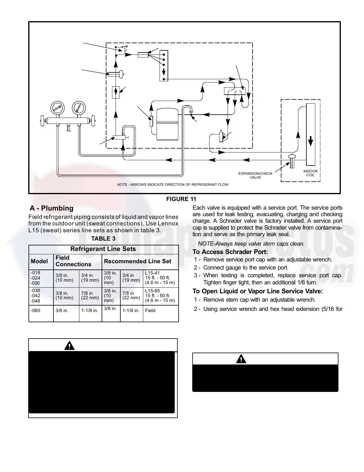
FIGURE 11
13HPX HEATING CYCLE (SHOWING MANIFOLD GAUGE CONNECTIONS)
OUTDOOR
COIL
DEFROST THERMOSTAT
EXPANSION/CHECK
VALVE
BIFLOW
FILTER / DRIER
TO
R−410A
DRUM
LOW
PRESSURE
HIGH
PRESSURE
COMPRESSOR
REVERSING VALVE
VAPOR
LINE
VALVE
MUFFLER
NOTE − ARROWS INDICATE DIRECTION OF REFRIGERANT FLOW
SERVICE
PORT
SUCTION
EXPANSION/CHECK
VALVE
INDOOR UNIT
OUTDOOR UNIT
LIQUID LINE
SERVICE
PORT
GAUGE MANIFOLD
DISTRIBUTOR
INDOOR
COIL
A − Plumbing
Field refrigerant piping consists of liquid and vapor lines
from the outdoor unit (sweat connections). Use Lennox
L15 (sweat) series line sets as shown in table 3.
TABLE 3
Refrigerant Line Sets
Model
Field
Connections
Recommended Line Set
−018
−024
−030
3/8 in.
(10 mm)
3/4 in
(19 mm)
3/8 in.
(10
mm)
3/4 in
(19 mm)
L15−41
15 ft. − 50 ft.
(4.6 m − 15 m)
−036
−042
−048
3/8 in.
(10 mm)
7/8 in
(22 mm)
3/8 in.
(10
mm)
7/8 in
(22 mm)
L15−65
15 ft. − 50 ft.
(4.6 m − 15 m)
−060
−061
3/8 in.
(10 mm)
1−1/8 in.
(29 mm)
3/8 in.
(10
mm)
1−1/8 in.
(29 mm)
Field
Fabricated
B − Service Valves
IMPORTANT
Only use Allen wrenches of sufficient hardness
(50Rc − Rockwell Harness Scale min). Fully in-
sert the wrench into the valve stem recess.
Service valve stems are factory torqued (from 9
ft lbs for small valves, to 25 ft lbs for large
valves) to prevent refrigerant loss during ship-
ping and handling. Using an Allen wrench rated
at less than 50Rc risks rounding or breaking off
the wrench, or stripping the valve stem recess.
The liquid and vapor line service valves (figures 12 and 13)
and gauge ports are accessible from outside the unit.
Each valve is equipped with a service port. The service ports
are used for leak testing, evacuating, charging and checking
charge. A Schrader valve is factory installed. A service port
cap is supplied to protect the Schrader valve from contamina-
tion and serve as the primary leak seal.
NOTE-Always keep valve stem caps clean.
To Access Schrader Port:
1 − Remove service port cap with an adjustable wrench.
2 − Connect gauge to the service port.
3 − When testing is completed, replace service port cap.
Tighten finger tight, then an additional 1/6 turn.
To Open Liquid or Vapor Line Service Valve:
1 − Remove stem cap with an adjustable wrench.
2 − Using service wrench and hex head extension (5/16 for
vapor line and 3/16 for liquid line), back the stem out coun-
terclockwise until the valve stem just touches the retaining
ring.
3 − Replace stem cap and tighten finger tight, then tighten an
additional 1/6 turn.
Do not attempt to backseat this valve. Attempts to
backseat this valve will cause snap ring to explode
from valve body under pressure of refrigerant.
Personal injury and unit damage will result.
DANGER
To Close Liquid or Vapor Line Service Valve:
1 − Remove stem cap with an adjustable wrench.
2 − Using service wrench and hex head extension (5/16 for
vapor line and 3/16 for liquid line), turn stem clockwise to
seat the valve. Tighten firmly.
 Loading...