Page 26
VII−WIRING AND SEQUENCE OF OPERATION
2
3
5
6
8
74
1
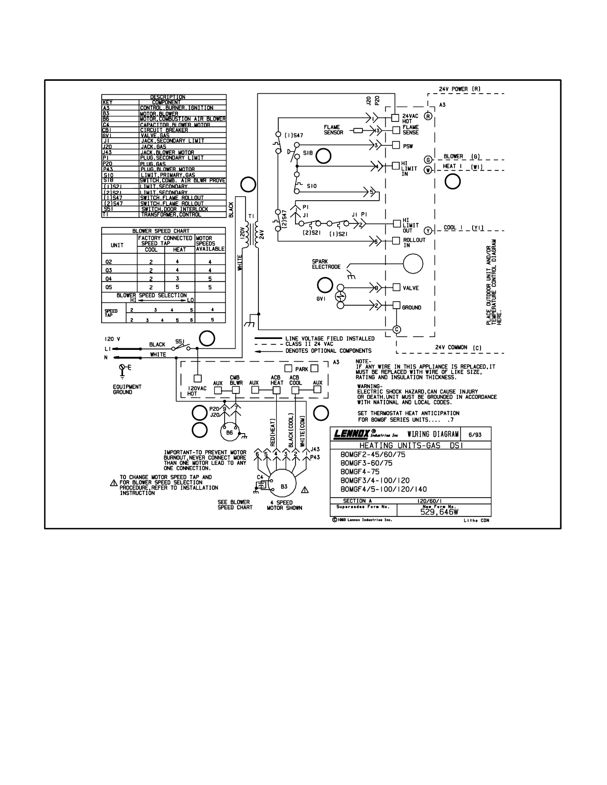
80MGF WITH RAM CONTROL
1- When disconnect is closed, 120V is routed through
door interlock switch (S51) to feed the line voltage
side of the furnace control (A3) and transformer T1 pri-
mary. Door interlock switch must be closed for A3 and
T1 to receive voltage.
2- T1 supplies 24VAC to terminal 24VAC" on A3. In turn,
terminal R" of A3 supplies 24VAC to terminal RC" of
the indoor thermostat (not shown).
3- When there is a call for heat, W1 of the thermostat en-
ergizes W of the furnace control with 24VAC.
4- CMB BLWR of the blower control energizes the com-
bustion air blower (B6). When the combustion air
blower nears full speed, combustion air prove switch
(S18) closes.
5- When S18 closes, assuming the flame rollout switch
(S47) primary limit (S10) and secondary limits (S21)
are closed, the furnace control begins a 45 second
time-delay (pre-purge).
6- At the end of the pre-purge cycle, the furnace control
simultaneously opens the gas valve and sends high
voltage to the spark electrode.
7- When flame is sensed, the furnace control begins a 45
second delay before energizing the indoor blower.
8- When heat demand is satisfied, W1 of the thermostat
de-energizes W of the furnace control and the furnace
control immediately de-energizes the gas valve. The
combustion air blower runs for 5 seconds (post-purge)
before being de-energized. Also, the indoor blower
runs for a designated period (90−240 seconds) as set
by switches on furnace control.
 Loading...


