Page 22
G−High Altitude Derate
NOTE−In Canada, certification for installation at alti-
tudes over 4500 ft. (1372m) above sea level is the juris-
diction of the local authorities.
80MGF−1 through −8 Models
This unit does not require gas pressure adjustment, or
pressure switch change when operating at elevations of 0
to 7500 ft. (0 to 2248m). Check gas line pressure with unit
firing. The minimum pressure as shown on the nameplate
for natural and propane gases must be maintained. No ori-
fice change is required.
NOTE−This is the only permissible field derate for this
appliance.
80MGF−9, −10 and −11 Models
Table 14 shows manifold pressure settings for installations
at different altitudes. Refer to table 15 for pressure switch
replacement for models at elevations of 4500 feet (1372m)
and greater.
TABLE 14
ALTITUDE
feet (m)
GAS FUEL
MANIFOLD
PRESSURE
in. W.C. (kPa)
0 − 4500
Natural 3.5 (0.87)
(0 − 1372)
Propane/LP 9.5 (2.36)
4500 − 5500
Natural 3.4 (0.86)
(1372 − 1676)
Propane/LP 9.2 (2.29)
5500 − 6500
Natural 3.3 (0.82)
(1676 − 1981)
Propane/LP 8.9 (2.21)
6500 − 7500
Natural 3.2 (0.80)
(1372 − 2286)
Propane/LP 8.6 (2.14)
TABLE 15
Unit Model Pressure Switch Part Number
80MGF−45 No Change
80MGF−60 No Change
80MGF−75 88J8001
80MGF−100 18L2401
80MGF−120 18L2401
80MGF−140 No Change
H−Flame Signal
A microamp DC meter is needed to check the flame signal
on the primary ignition control.
Flame (microamp) signal is an electrical current which
passes from the furnace control through the sensor elec-
trode during unit operation. Current passes from the sen-
sor through the flame to ground to complete a safety cir-
cuit.
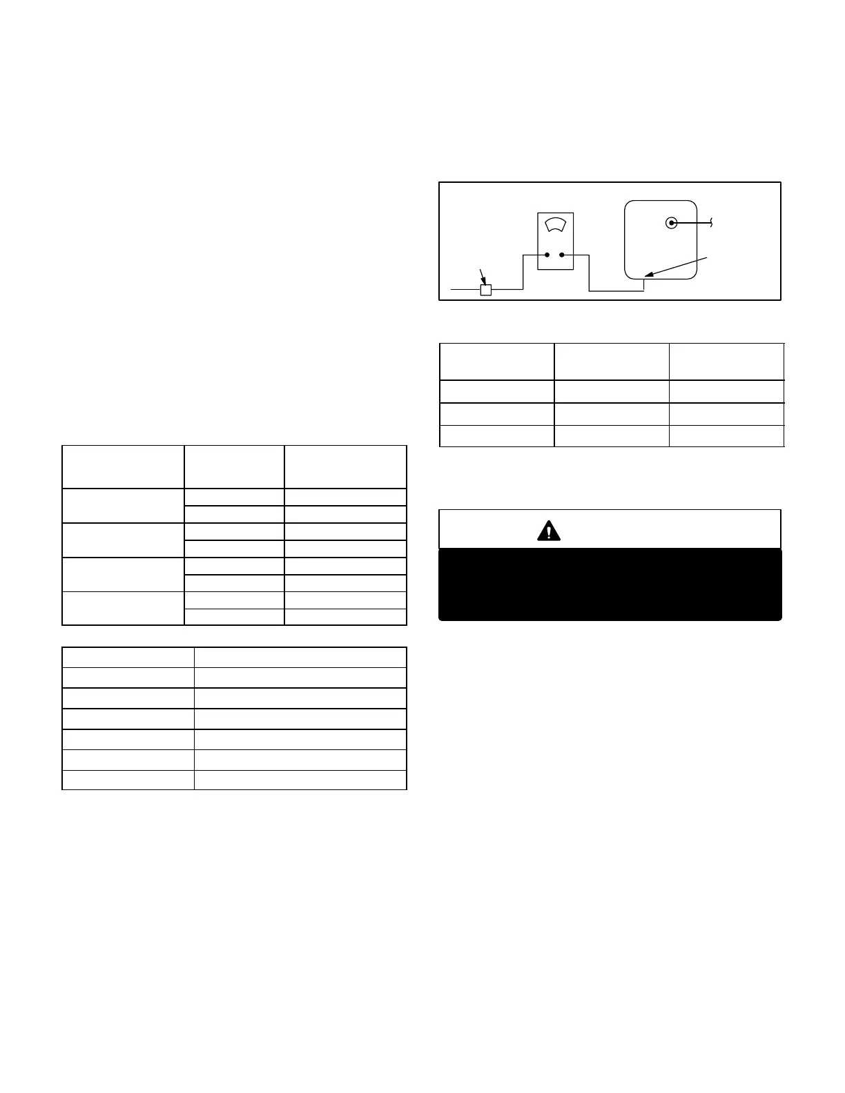
To Measure Flame Signal:
1− Place meter in series between furnace control and
sensor wire. Connect the positive (+) lead of meter to
the ignition control sensor connection and the nega-
tive (−) lead of the meter to the sensor wire. See figure
23.
2− Set thermostat for a heating demand and check flame
signal with unit operating. See table 16 for microamp
reading for the various control boards used.
FLAME SIGNAL TEST
FIGURE 23
IGNITION
CON-
TROL
SENSE"
TERMINAL
SENSOR
WIRE
D.C. MICROAMP
METER
FLAME
SENSOR
TABLE 16
CONTROL
MICROAMP
SIGNAL
DROP OUT
SIGNAL
Ram 1.0 to 5.0 t1.0
EGC 1.0 to 5.0 v.45
SureLight w.70 v.15
Flame signal may rise above 5 microamps for the first few
seconds after ignition then level off within the range.
WARNING
Fire and explosion hazard.
These instructions MUST be followed exactly.
Can cause a fire or explosion resulting in property
damage, personal injury or loss of life.
V−TYPICAL OPERATING CHARACTERISTICS
A−Blower Operation and Adjustment
NOTE− The following is a generalized procedure and
does not apply to all thermostat controls.
1− Blower operation is dependent on thermostat control
system.
2− Generally, blower operation is set at thermostat sub-
base fan switch. With fan switch in ON position, blower
operates continuously on heating speed. With fan
switch in AUTO position, blower cycles with demand or
runs continuously while heating or cooling circuit cycles.
3− Depending on the type of indoor thermostat, blower
and entire unit will be off when the system switch is in
OFF position.
B−Temperature Rise
Temperature rise for 80MGF units depends on unit input,
blower speed, blower horsepower and static pressure as
marked on the unit rating plate. The blower speed must be
set for unit operation within the range of AIR TEMP. RISE
°F" listed on the unit rating plate.
 Loading...


