FIGURE 24
STATIC PRESSURE
TEST
MANOMETER
80MGF UNIT
Page 23
To Measure Temperature Rise:
1 − Place plenum thermometers in the supply and return
air plenums. Locate supply air thermometer in the first
horizontal run of the plenum where it will not pick up ra-
diant heat from the heat exchanger.
2 − Set thermostat to highest setting.
3 − After plenum thermometers have reached their high-
est and steadiest readings, subtract the two readings.
The difference should be in the range listed on the unit
rating plate. If the temperature is too low, decrease
blower speed. If temperature is too high, first check
the firing rate. Provided the firing rate is acceptable, in-
crease blower speed to reduce temperature. To
change blower speed taps see the Blower Speed Taps
section in this manual.
C−External Static Pressure
1 − Measure tap locations as shown in figure 24.
2 − Punch a 1/4" diameter hole
in supply and return air ple-
nums. Insert manometer
hose flush with inside edge
of hole or insulation. Seal
around the hose with per-
magum. Connect the zero
end of the manometer to the
discharge (supply) side of the system. On ducted sys-
tems, connect the other end of manometer to the re-
turn duct as above. For systems with non−ducted re-
turns, leave the other end of the manometer open to
the atmosphere.
3 − With only the blower motor running and the evaporator
coil dry, observe the manometer reading. Adjust blow-
er motor speed to deliver the air desired according to
the job requirements.
4 − External static pressure drop must not be more than
0.5" W.C.
5 − Seal around the hole when the check is complete.
D−Blower Speed Taps Leadless Motors
Blower speed tap selection is accomplished by changing the
taps at the blower motor harness connector. Disconnect har-
ness connector from motor to expose speed selectors.
Blower speed selections are listed in table 17.
To Change Blower Speed:
1 − Turn off electric power to furnace.
2 − Remove front panel and blower access door. See
figure 4.
3 − Disconnect blower motor harness from motor.
4 − Select desired speeds for heating and cooling. (Red =
heating, Black = cooling, White = common). See table
17.
TABLE 17
BLOWER SPEED SELECTION
Unit
Factory Connected
Speed Taps
Speeds
Cool (Black) Heat (Red)
va
a
e
80MGF2-45 2 4 4
80MGF2-60 2 4 4
80MGF3-60 2 4 4
80MGF2-75 2 3 4
80MGF3-75 2 4 4
80MGF4-75 2 4 5
80MGF3/4-100 2 4 5
80MGF4/5-100 2 5 5
80MGF3/4-120 2 3 5
80MGF4/5-120 2 5 5
80MGF4/5-140 2 3 5
BLOWER SPEED SELECTION
HI LOW
2345
23456
4
5
◊
◊
◊
MOTOR PLUG SPEED TAP DESIGNATION
234
◊
3
TABLE 18
TAPS AVAILABLE
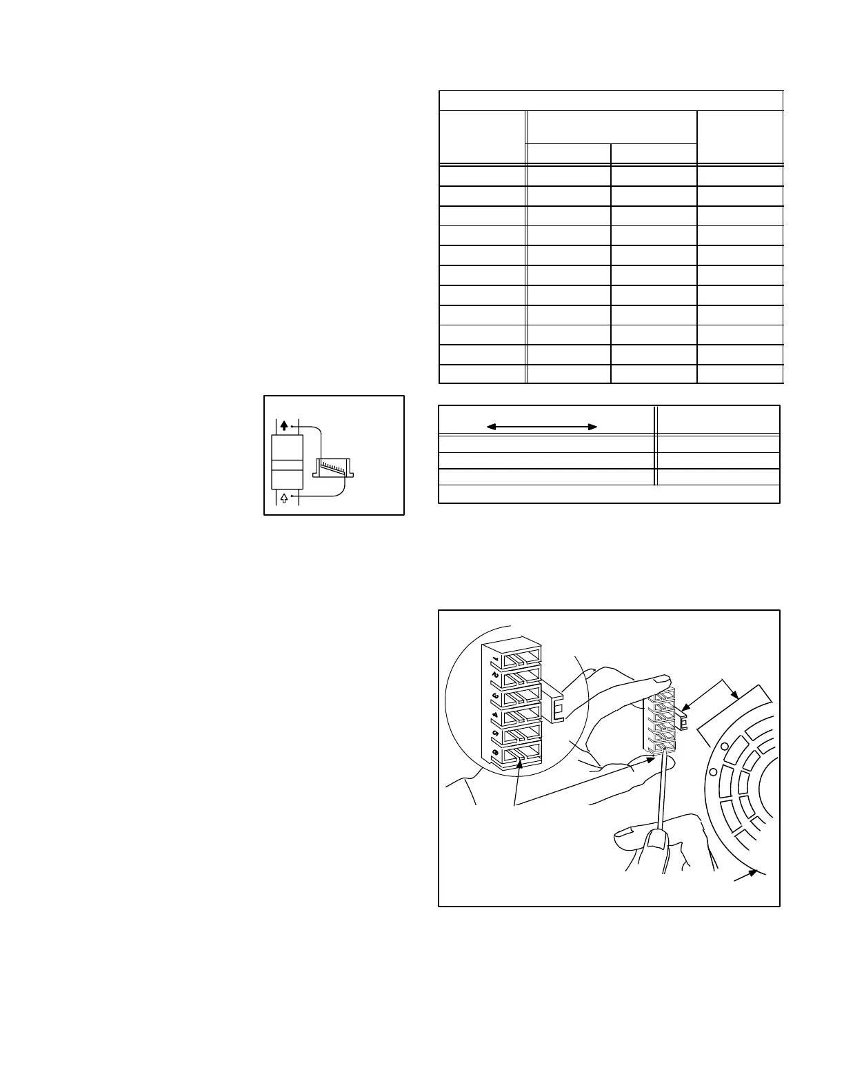
5 − Depress harness connector tab to release wire termi-
nal. Select connector location for new speed (refer to
unit wiring diagram). Insert wire terminal until it is se-
curely in place. See figure 25.
6 − Replace harness connector to motor.
BLOWER SPEED TAP SELEC-
TION
Leadless motors only
FIGURE 25
HARNESS
CONNECTOR
MOTOR
DEPRESS TAB TO RELEASE
WIRE TERMINAL. SELECT
CONNECTOR LOCATION FOR
NEW SPEED (REFER TO UNIT
WIRING DIAGRAM). INSERT
WIRE UNTIL IT IS SECURELY
IN PLACE.
 Loading...


