Page 24
E−Blower Speed Taps Leaded Motors
−11 Models
Blower speed tap changes are made on the SureLight
control board. See figure 8. Unused taps must be secured
on dummy terminals "PARK M1" and or "PARK M2" on the
SureLight board. The heating tap is connected to the "ACB
HEAT " terminal and the cooling tap is connected to the
"ACB COOL" terminal. The continuous blower tap is con-
nected to the "ACB LOW" terminal.
To change existing heat tap, turn off power then switch out
speed tap on "ACB HEAT" with tap connected to "PARK
M1" or "PARK M2". See table 19 for blower motor tap col-
ors for each speed.
TABLE 19
VI−MAINTENANCE
At the beginning of each heating season, the system
should be checked as follows:
Filters
All 80MGF filters are installed external to the unit. Filters
should be inspected monthly and cleaned or replaced
when necessary to assure proper furnace operation. See
table 20 for filter sizes. Replacement filters for
80MGF-45/60/75 units must have a minimum velocity rat-
ing of 400 FPM. Replacement filters for
80MGF-100/120/140 units require a minimum velocity rat-
ing of 625 FPM.
TABLE 20
MODEL NUMBER FILTER SIZE
80MGF−45/60/75 16" X 20" X 1"
80MGF−100/120/140 20" X 20" X 1"
WARNING
Blower door must be securely in place when blow-
er and burners are operating. Gas fumes, which
could contain carbon monoxide, can be drawn
into living space resulting in personal injury or
death.
A−Cleaning Heat Exchanger and Burners
NOTE−Use papers or protective covering in front of fur-
nace while cleaning furnace.
Due to dimples designed in the heatexchanger, cleaning is
not recommended. Removal is for inspection only.
Burners
Burners and burner flame should be inspected at the be-
ginning of each heating season. Clean burners, if neces-
sary, as outlined below:
1 − Turn off electrical and gas supply to unit.
2 − Remove burner box top.
3 − Remove burner retaining bracket.
4 − Remove burners.
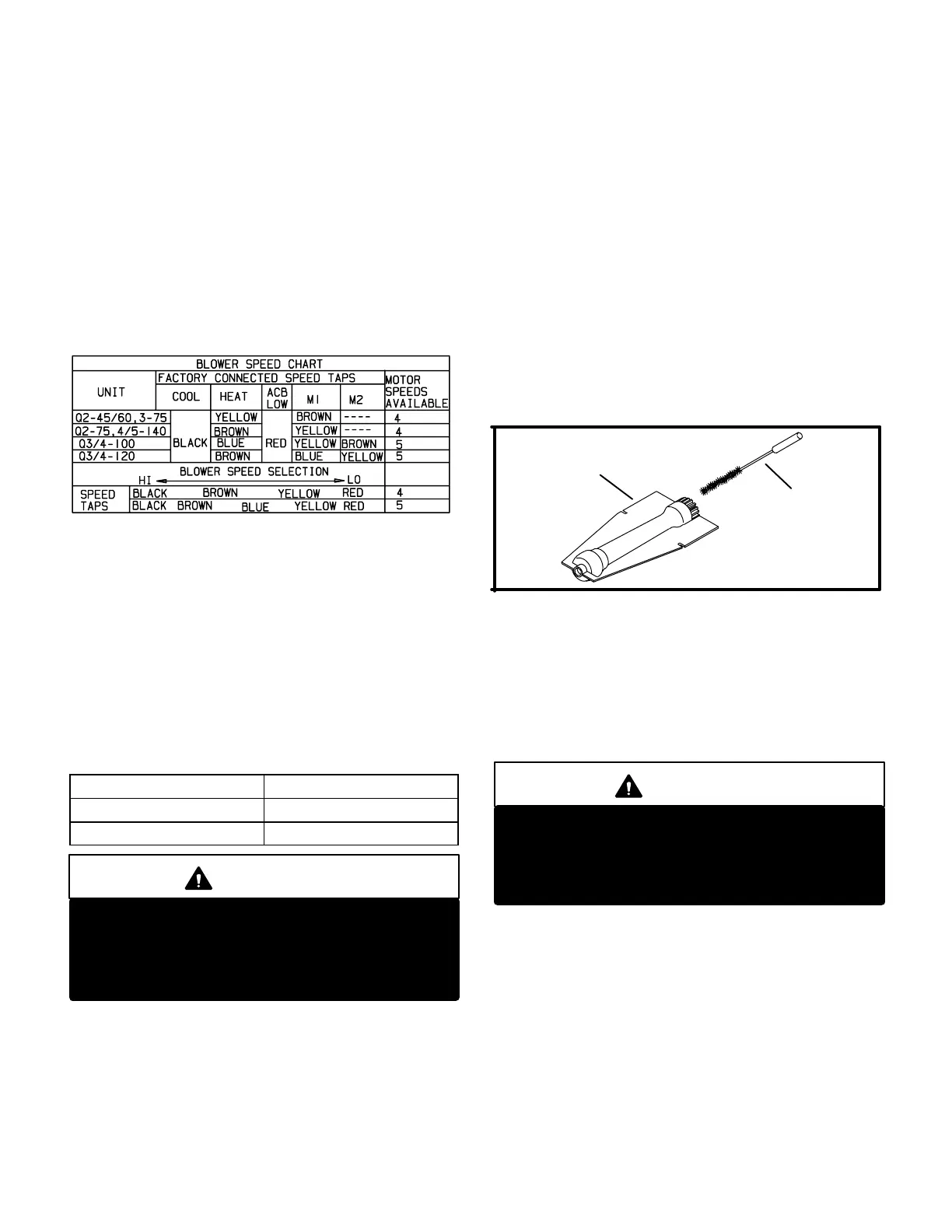
5 − Clean burner insert with bottle brush as shown in fig-
ure 26.
NOTE−Use papers or protective covering in front of fur-
nace while cleaning furnace.
FIGURE 26
CLEANING BURNERS
BOTTLE
BRUSH
BURNER
6 − Use bottle brush to clean inside of each burner.
7 − Replace burners and burner retaining bracket, mak-
ing sure burners are properly seated in slots on tray
and orifice in manifold.
8 − Check electrode gap using appropriately sized twist
drills or feeler gauges. Gap should be between 2.79 to
3.56mm (0.110 and 0.140 inches).
9 − Reinstall burner box top.
CAUTION
Some soaps used for leak detection are corrosive
to certain metals. Carefully rinse piping thorough-
ly after leak test has been completed. Do not use
matches, candles, flame or other sources of igni-
tion to check for gas leaks.
10 − Restore electrical power and gas supply. Follow light-
ing instructions on front of unit. Check the following:
appearance of burner flame, burner pressure, gas flow
and temperature rise. Make adjustments, if necessary.
See adjustments section.
B−Supply Air Blower
1 − Check and clean blower wheel.
2 − Motors used on the Lennox 80MGF series units are
permanently lubricated and need no further lu-
brication.
 Loading...


