Page 8
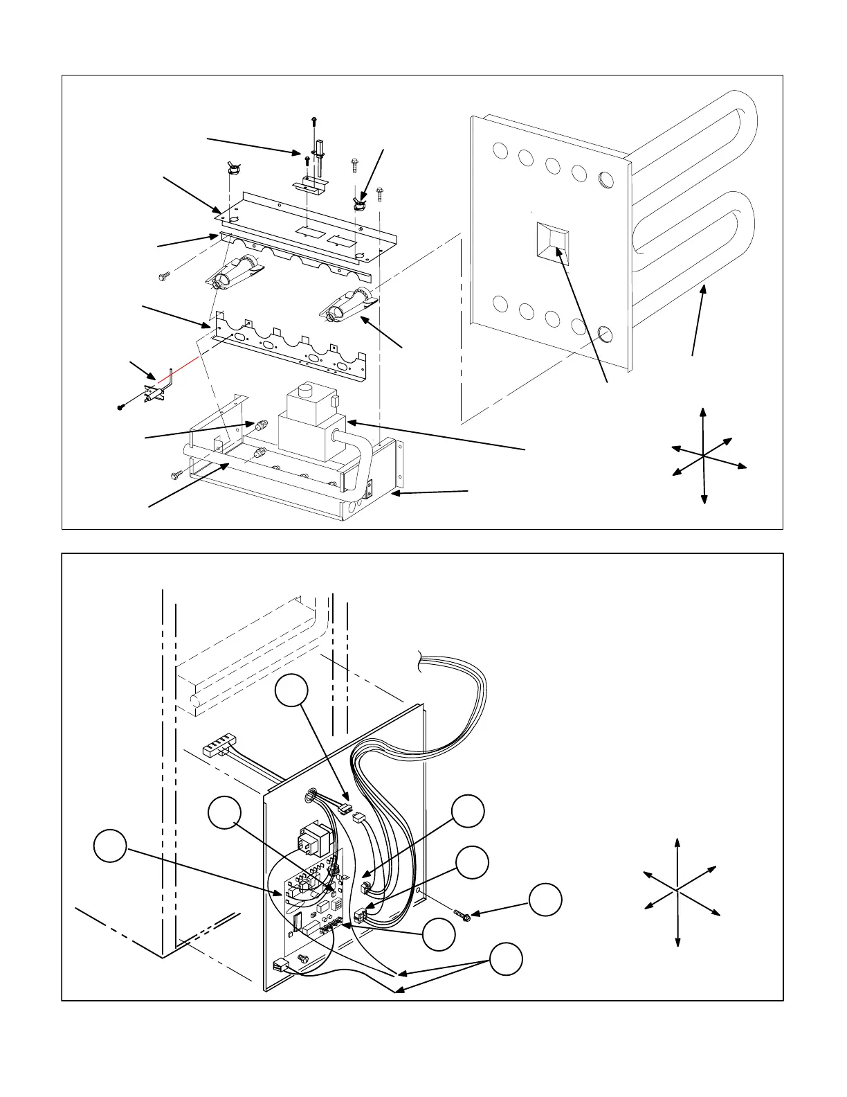
FIGURE 3
Top
80MGF BURNER ASSEMBLY
(Shown With SureLight ignitor)
FLAME
SENSOR
MANIFOLD
ORIFICE
GAS VALVE
HEAT EXCHANGER
VEST PANEL
BURNER
UPPER
BURNER
MOUNTING
RAIL
LOWER
BURNER
MOUNTING
RAIL
BURNER BOX
BURNER BOX
TOP
Front
Right
Bottom
Left
Back
PRIMARY LIMIT
ROLLOUT
SWITCHES
SURELIGHT
IGNITOR
FIGURE 4
80MGF BLOWER DOOR COMPONENTS − BLOWER ACCESS
(SureLight MODEL SHOWN)
1
5
8
To Access Blower:
1− Turn off power to unit and disconnect L1 and L2
line voltage power.
2− Disconnect thermostat wiring connections
from furnace control board.
3− Disconnect blower leads from control board.
4− Disconnect J1 from P1.
5− Disconnect 6 pin P156 from control board.
6− Disconnect 9 pin P58 from control board.
7− Disconnect sensor wiire from center of board.
8− Remove screws (2) and lift panel from unit.
2
Top
Bottom
Left
Right
Front
3
4
6
Back
7
 Loading...


