• 21 •
AQUALEAN - AWC/AWH - MIL118E-1407 / 10-2013
Service
panel
Standard
On site
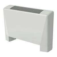
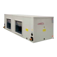
AIRFLOW CONFIGURATION.
Units are assembled with supply airfl ow confi guration on the side (90º angle to the return).
On site, the fan can easily be repositioned for an in-line supply.
For models AWC/H 018-020 the additional sheet metal parts and fan support are not needed and can be removed.
See picture below for airfl ow confi guration.
CIRCULATION PUMP ALIMENTATION.
It is possible to connect a circulation pump to the unit and to power it. 230 V supply, maximum 1A. See electrical folio
delivered with the unit to know where it should be connected.
DISTANCE CONTROL.
It is possible to switch to stand by mode from a distance. See electrical folio delivered with the unit to know where it
should be connected.
ON/OFF SIGNAL SUPPLY.
It is possible to send ON/OFF signal indicating whether the compressor is engaged.
To do so it is possible to connect to J14 plug and to modify the alarm by this information using a DS60 expert menu. It
should be asked and done while commissioning the unit by a certifi ed Lennox technician.
It is also possible to connect to the circulation pump connection. But the connection is supplied with 230V. It would be
necessary to install a relay to get a on/off volt free contact.
SENDING A 0-10 V SIGNAL (FOR EXAMPLE TO CONTROL A VALVE).
When the customer wants to connect a valve to regulate the unit operation, Lennox do recommend to select the Low
Water Loop option which includes a 3-way valve (with possibility to convert to a 2-way valve by closing the B-gate) as
well as a high pressure transducer. To export a 0-10V signal for another application, it is necessary to ask for a com-
missioning by a Lennox certifi ed technician.
SENDING A 230 V 3 POINTS SIGNAL (FOR EXAMPLE TO CONTROL A VALVE).
When the customer wants to connect a valve to regulate the unit operation, Lennox do recommend to select the Low
Water Loop option which includes a 3-way valve (with possibility to convert to a 2-way valve by closing the B-gate) as
well as a high pressure transducer. To export a 230V 3 points signal for another application, it is necessary to ask for a
commissioning by a Lennox certifi ed technician.
AIRFLOW CHANGE (UNITS 007 to
020):
1- Unscrew and remove the unit´s roof
2- Unscrew and remove access panel
3- Properly cut and remove the insulation
material located behind the access panel
4- Install the insulation material inside the
service panel (Alu scotch)
5- Unscrew the srews used to positioned
the fan
6- On model 018 and 020 remove the
additional support metal sheet
7- Turn the fan so that it will be positioned
in line
8- Fix the fan with the screws
9- Screw the access panel on the side
of the unit in order to close the original
supply area.
Standard
On site
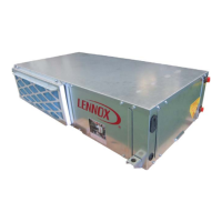
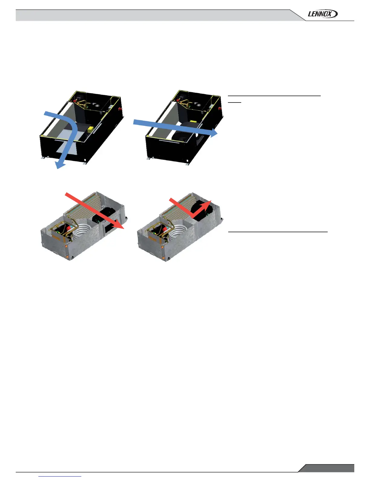
AIRFLOW CHANGE (UNITS 002-003):
1- Unscrew both lateral + fan and end
panel.
2- Swap the panel´s positions.
3- Fix them to the structure.
Lateral
panel +
fan.
End panel
Lateral
panel + fan.
End panel
(UNITS 007 to 020) (UNITS 007 to 020)
(UNITS 002-003)
(UNITS 002-003)
Service
panel
OTHER FUNCTIONALITIES
 Loading...