BALTIC R410A-IOM-0708-E Page 26
THIS WORK MUST ONLY BE CARRIED OUT
BY TRAINED REFRIGERATION ENGINEERS
FILL THE COMMISSIONNING SHEET AS YOU GO
ALONG
ELECTRICAL CONNECTIONS
Ensure that the power supply between the building and the
unit meets local authority standards and that the cable
specification satisfies the start-up and operating conditions.
ENSURE THAT THE POWER SUPPLY
INCLUDES 3 PHASES
(+ NEUTRAL if the unit is equipped with the
power exhaust fan)
Check the following wire connections for tightness:
Main switch connections, mains wires linked to the
contactors and circuit breakers and the cables in the
24V control supply circuit.
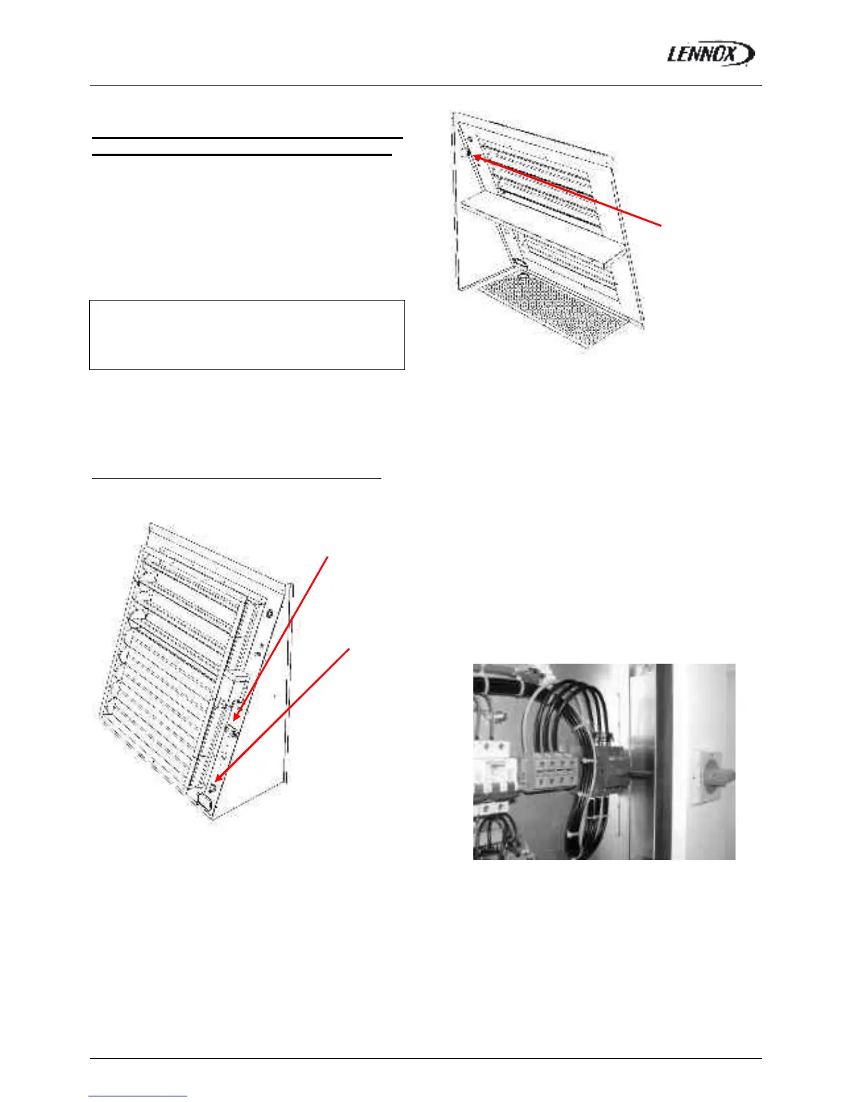
How to connect roof curbs and energy recovery module
Cables and their connectors corresponding to the roof curb’
motor and actuator and extraction box’ ones are already
rolled up in these elements; it is enough to bring them
through the openings envisaged and to connect them on
the sites indicated on the figure 28.
It’s the same procedure when you have an energy recovery
module.
PRELIMINARY CHECKS
Ensure that all drive motors are secure.
Ensure that the adjustable pulley blocks are secure and
that the belt is tensioned with the transmission correctly
aligned. Refer to the next section foe details.
Using the electrical wiring diagram, check the
conformity of the electrical safety devices (circuit
breaker settings, presence and rating of fuses).
Check the temperature probe connections.
Fig.29
Connector for the roof
curb motor or the
extraction box’ one
Connector for the roof
curb actuator or the
extraction box’ one
Connector for the
energy recovery
module + Fresh air
sensor
Fig. 28
 Loading...