18
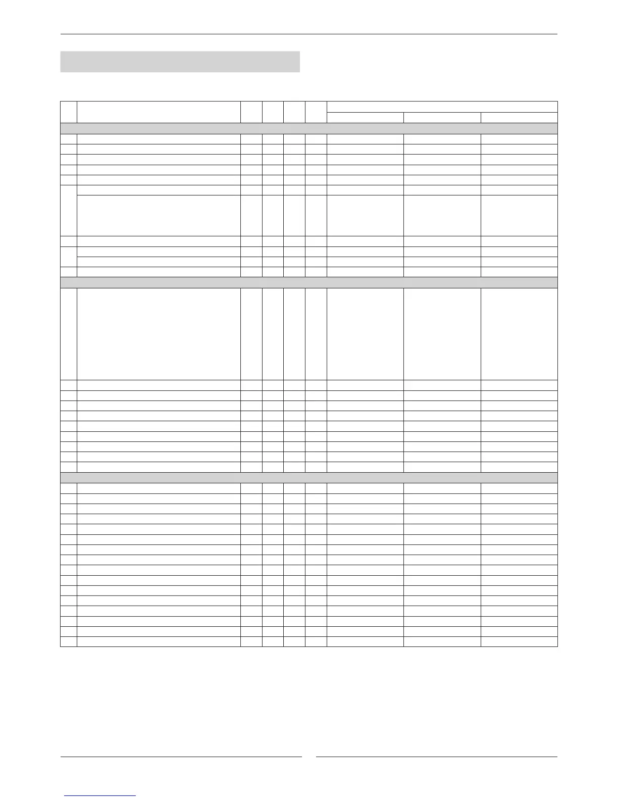
A01 A7 A4 0.1 ºC 3,0 2 ------
A02 0,3 122 0.1 ºC 5,0 5 ------
A03 0 150 1 0 30 ------
A04 A1 R16 0.1 ºC 4,5 ------ ------
A05 0,3 50 0.1 ºC 1,0 ------ ------
A08
A1 R16 0.1 ºC 35 ------ ------
0 20 0.1 ºC ------
1.5 (ANCM)
------
2.5 (ANHM 22E-43E)
3.5 (ANHM 52D-86D)
4.5 (ANHM 112D-152D)
A9 0 20 0.1 ºC 1 1 ------
A11
A1 R16 0.1 ºC 33 ------ ------
0 20 0.1 ºC ------ 2.5 (ANCM 52D-86D) ------
A13 A7 R16 0.1 ºC ------ 7 ------
b0 0 11 1 N 0 11 10
b1 ------ ------ ------ ºC
b2 ------ ------ ------ ºC
b3 ------ ------ ------ ºC
b4 ------ ------ ------ ºC/bar
b5 ------ ------ ------ ºC
b6 ------ ------ ------ ºC
b7 ------ ------ ------ ºC
b8 ------ ------ ------ ºC/bar
b21 ------ ------ ------ ºC
C01 0 999 1 0 0 0
C02 0 999 1 120 120 120
C03 0 999 1 300 300 300
C04 0 999 1 2 2 2
C05 0 999 1 0 0 0
C06 0 999 1 5 5 5
C07 0 999 1 150 0 0
C08 0 150 1 4 0 0
C10 0 8000 100
C11 0 8000 100
C12 0 8000 100
C13 0 8000 100
C14 0 100 100 0 0 0
C15 0 8000 100
C17 0 150 1
0 0 0
C18 0 150 1
0 1 0
PARAMETERS
PAR.
DESCRIPTION MIN. MAX. VAR. UD.
BY DEFAULT
ECOLEAN AIRCOOLAIR AIRCUBE
Antifreeze and electrical heater
Antifreeze alarm set point.
Antifreeze differential.
By-pass time for antifreeze alarm. sec.
Antifreeze heater set point.
Antifreeze heater differential.
Auxiliary heater absolute set point (1
st
step).
Auxiliary heater relative set point (1
st
step).
Auxiliary heater differential.
Auxiliary heater absolute set point (2
st
step).
Auxiliary heater relative set point (1
st
step).
Lower discharge air temperature in freecooling.
Probes
Cong. of probe to be shown on the display:
0= probe B1. 1= probe B2
2= probe B3. 3= probe B4
4= probe B5. 5= probe B6
6= probe B7. 7= probe B8
8= Set point without compensation.
9= Dynamic set point with possible compensation.
10= Remote ON/OFF digital input status.
11= Terminal DC40 probe.
Probe B1.
Probe B2.
Probe B3.
Probe B4
Probe B5.
Probe B6.
Probe B7.
Probe B8.
Probe DC40.
Timming and delays
Min. compressor ON time. sec.
Min. compressor OFF time. sec.
Delay between 2 starts of the same compressor. sec.
Delay between starts of the 2 compressor. sec.
Delay between 2 shut-downs of the 2 compressors. sec.
Delay at start up. sec.
Delay in switching on the compressor after switching on the pump.
sec.
Delay in switching off the compressor after switching off the pump. min.
Compressor 1 timer. hours
Compressor 2 timer. hours
Compressor 3 timer. hours
Compressor 4 timer. hours
Compressor operation timer threshold (0=not used). hours
Evaporator pump timer. hours
Minimum time between 2 pump starts.
min.
Minimum pump/indoor fan ON time.
min.

 Loading...
