22
GND
TX+
TX-
GO
G
ASSEMBLY AND INSTALLATION INSTRUCTIONS
DC40.
Installation instructions
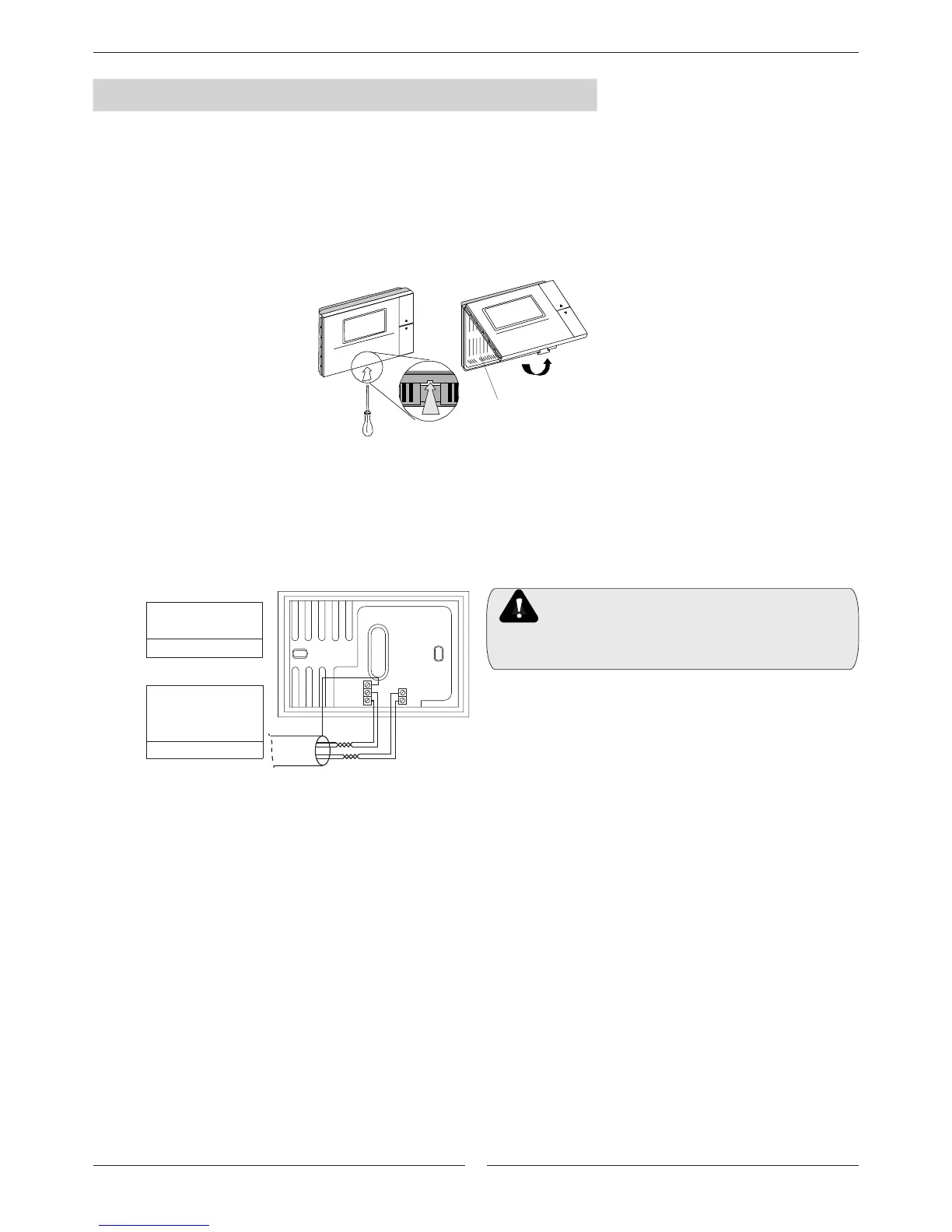
1. Separate the cover of the instrument from the bodypart using a screwdriver as shown in Fig. 8.1.
2. Open the instrument with a “hinge” movement, pivoting the cover of the instrument upwards.
Lower view
Fig. 8.1
Fig. 8.2
3. Fix the rear part to the wall, taking care that the connection cables pass through the hole in the centre of the rear casing.
The distances between the fastening holes are designed so as to be able to t the DC40 to a ush-mounting connection box
compliant with the CEI C.431 - IEC 670 standards. If this is not available, use the fastening holes on the casing as a guide
for drilling the holes in the wall, and then use the kit of screws and plugs supplied.
4. Connect the cables to the terminals located in the casing as indicated in the casing itself or in the electrical diagram.
5. Once the installation is complete, t the terminal onto the casing by pivoting the cover with a “hinge” movement and close it.
When closing, make sure that the pins on the board t into the corresponding terminals.
Installation warnings
- Disconnect the power supply before working on the DC40 during operations of assembly, maintenance and replacement.
- The terminal must be fastened to the wall in such a way as to allow the circulation of air through the slits on the rear casing.
- Avoid installing the boards in environments with the following characteristics:
- Avoid locations where there is a great variation in room temperature.
- Near doors leading to the outside.
- On outside walls.
- Where it will be exposed to direct sunlight or to conditioned air ow.
- Where there are strong magnetic and/or radio frequency interference (for example, near transmitting antennae).
Keep the DC40’s inductive load cables separate from
those of any power devices (contactors, etc.) in order to
prevent electromagnetic interference.
Do not lay power and communications cables together
- Run a connection from the electrical box in the outdoor unit to
the DC40 device:
. 91 and 92 terminal blocks respectively to Tx+ and Tx-
(Twisted pair for communications).
. 93 and 94 terminal blocks respectively to GO and G.
(Twisted pair for 24VAC power).
. 90 to GND. (shield).
2 x TWISTED PAIR
SCREEN WIRE AWG20
L.max=100m
1 x TWISTED PAIR
SCREEN WIRE AWG20
+ 2 x 1,5 mm
2
L.max=200m

 Loading...
