-00
84
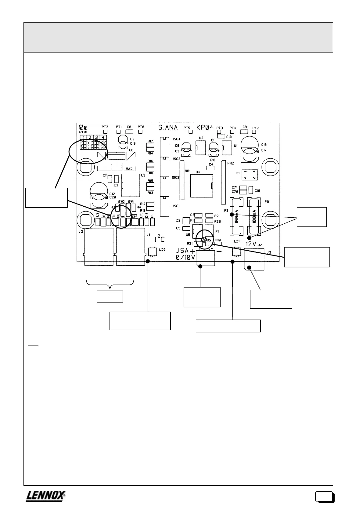
EXTENSION ANALOGUE OUTPUT ØØ KP04
The KP04 card provides, via a digital/analogue converter, analogue output (0-10V), resolution 39mV.
It is possible to connect up to 4 KP04 extensions to the same CPU, which offers a maximum capacity of 2 + 4 x
1 = 6 analogue outputs.
The card is calibrated by adjusting the potentiometer P1.
Key :
J1, J2: RJ45 connectors of the Bus I²C
J3: 2 point removable pin connector, pitch 5.08 for external 12Vac supply
J4 (JAS.): 2 point removable pin connector, pitch 3.81 for analogue output 0-10V
SW1, SW2: Switches for configuration of the card address
The position of jumpers for each configuration is marked on the card.
LD1: LED presence of power
LD2: LED presence of dialogue
P1: Potentiometer for card calibration (adjustment of amplitude)
PT1: Earth
PT2: VRF
PT3: +12V isolated
PT4: 0V isolated
PT5: +5V isolated
PT6: Vcc (+5V)
PT7: +12V rectified and filtered (before adjustment)
100mAT
fuses
LED presence of I²C
connection
Calibration
potentiometer
12Vac
supply
Analogue
output
Addressing
configuration
LED power on
I²C Bus
 Loading...

