Page 10
2 - Approach temperature should be as indicated in
table 3 for each stage. An approach temperature
greater than this value indicates an undercharge.
An approach temperature less than this value
indicates an overcharge.
A - Add or remove charge in increments.
B - Allow system to stabilize at least 5 minutes each
time refrigerant is added or removed.
3 - Do not use the approach method if system pressures
do not match pressures in table 4 except when the
outdoor ambient temperature is below 65ºF (18ºC).
The approach method is not valid for grossly over or
undercharged systems.
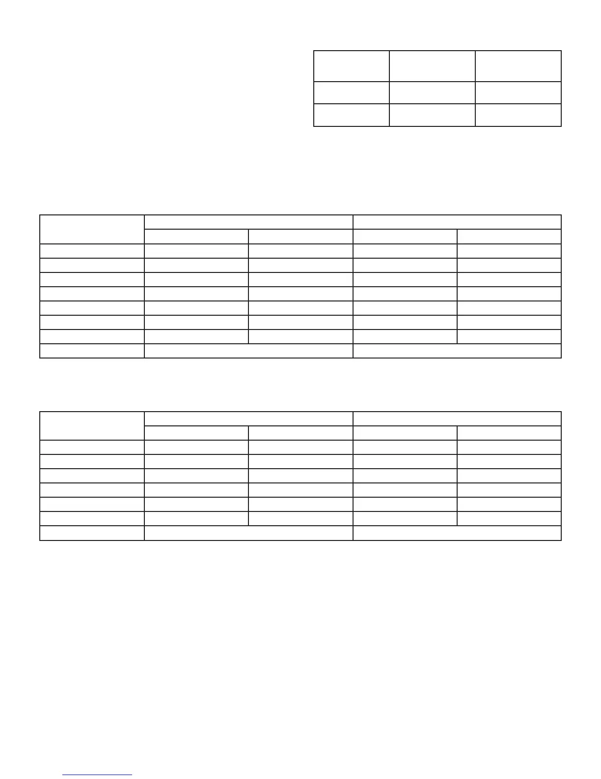
TABLE 3. HFC-410A Approach Temperatures*
Models
Approach
Temperature (ºF)
(+/-1)
Approach
Temperature (ºC)
(+/-.05)
ELP090S4S /
ELA090
7.0 3.9
ELP120S4S /
ELA120
6.0 3.3
*Approach temperature method valid at full load.
TABLE 4. HFC-410A Normal Operating Pressures – Cooling Mode (Liquid ±10 and Suction ±5 psig)**
Temp*
ELP090 / ELA090 ELP120 / ELA120
Liquid Suction Liquid Suction
65º F (18º C) 226 119 247 132
75º F (24º C) 261 125 291 136
85º F (29º C) 303 129 333 138
95º F (35º C) 349 133 370 140
105º F (41º C) 404 135 437 142
115º F (46º C) 462 137 495 144
125º F (52º C) 525 136 562 146
STD. CFM 2760 4000
*Temperature of air entering outdoor coil.
Liquid and suction pressures measured via condenser service valve ports.
** Indoor conditions – 80° F Dry Bulb and 67° F Wet Bulb.
TABLE 5. HFC-410A Normal Operating Pressures – Heating Mode (Liquid ±10 and Suction ±5 psig)**
Temp*
ELP090 / ELA090 ELP120 / ELA120
Liquid Suction Liquid Suction
60º F (15º C) 364 121 335 115
50º F (10º C) 343 100 322 101
40º F (4º C) 324 83 308 86
30º F (-1º C) 311 72 294 72
20º F (-6º C) 297 57 280 58
10º F (-12º C) 280 44 266 44
STD. CFM 2760 4000
*Temperature of air entering outdoor coil.
Liquid and suction pressures measured via condenser service valve ports.
** Indoor conditions – 70° F.
 Loading...