Page 5
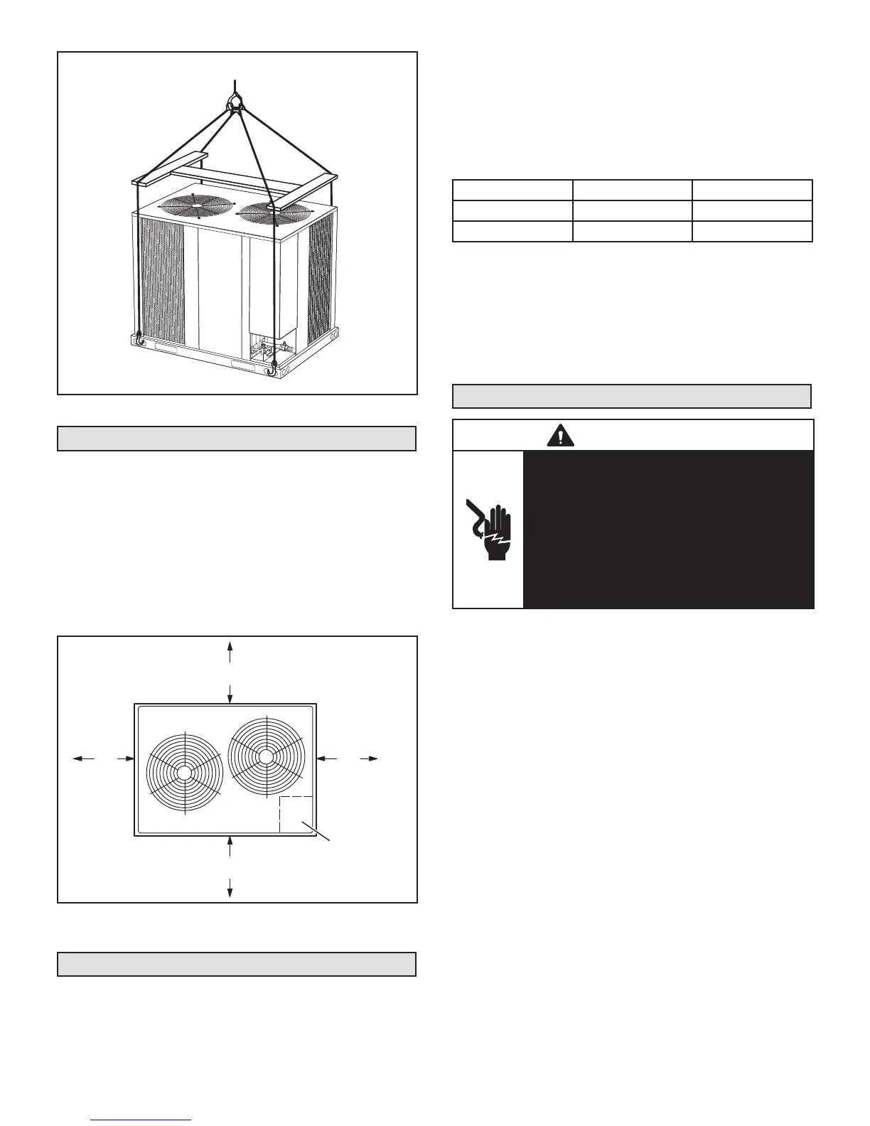
Caution - do not
walk on unit
.
Lifting point should be directly above the center of gravity.
Important - all panels
must be in place for
rigging.
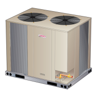
FIGURE 1. ELP090S4S and ELP120S4S
Installation Clearances
See Unit Dimensions on page 2 for sizing mounting slab,
platforms or supports. Refer to gures 4 through 6 for
mandatory installation clearance requirements.
NOTES:
• Clearance to one of the remaining two sides may be 12
in. (305 mm) and the nal side may be 6 in. (152 mm).
• A clearance of 24 in. (610 mm) must be maintained be-
tween two units.
• 48 in. (1219 mm) clearance required on top of unit.
CONTROL BOX
ACCESS
SEE
NOTES
SEE
NOTES
36”
30”
FIGURE 2. ELP090S4S and ELP120S4S
Installation Clearances
Line Set
Field refrigerant piping consists of liquid and suction lines
connecting the condensing unit and the indoor unit. Liquid
and suction service valves are located in a compartment
at the corner of the unit below the control box.
Piping can be routed directly from the service valves or
eld supplied elbows can be added to divert the piping as
required.
Refer to table 1 for eld-fabricated refrigerant line sizes for
runs up to 50 linear feet (15 m).
TABLE 1. Refrigerant Line Sizes for Runs
Up to 50 Linear Feet
Unit Liquid Line Suction Line
ELP090 5/8” (16mm) 1-1/8” (29mm)
ELP120 5/8" (16mm) 1-1/8” (29mm)
Refrigerant Line Limitations
You may install the unit in applications that have line set
lengths of up to 50 linear feet (15 m) with refrigerant line
sizes as outlined in table 1 (excluding equivalent length of
ttings). Size refrigerant lines greater than 50 linear feet
(15m or greater) according to the Lennox Refrigerant Pip-
ing Design and Fabrication Guidelines (Corp. 9351-L9) or
latest version.
Electrical Connections
WARNING
Electric Shock Hazard. Can cause injury or
death. Unit must be properly grounded in
accordance with national and local codes.
Line voltage is present at all components
when unit is not in operation on units with
single-pole contactors. Disconnect all remote
electric power supplies before opening
access panel. Unit may have multiple power
supplies.
In the United States, wiring must conform with current lo-
cal codes and the current National Electric Code (NEC). In
Canada, wiring must conform with current local codes and
the current Canadian Electrical Code (CEC).
TRANSFORMER – 24VAC, 70VA – PROVIDED
NOTE – The addition of accessories to the system could
exceed the 70VA power requirement of the factory-pro-
vided transformer. Measure the system’s current and
voltage after installation is complete to determine trans-
former loading. If loading exceeds the factory-provided
transformer capacity, a larger eld-provided transformer
will need to be installed in the system.
 Loading...