Page 6
Refer to the unit nameplate for minimum circuit ampacity amperage
minimum, and maximum fuse or circuit breaker fusible (HACR per
NEC). Install power wiring and properly sized disconnect switch.
NOTE —
UNITS ARE APPROVED FOR USE ONLY WITH COPPER
CONDUCTORS. GROUND UNIT AT DISCONNECT SWITCH OR TO AN EARTH
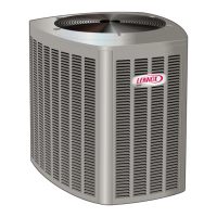
CIRCUIT SIZING AND DISCONNECT SWITCH
DISCONNECT
SWITCH
MAIN FUSE
BOX/BREAKER
PANEL
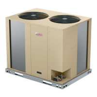
K1 CONTACTOR
LEFT CUTOUT
HIGH VOLTAGE WIRING
GROUND LUG
CONTROL BOX
USE THE LEFT CUTOUT TO ROUTE
HIGH VOLTAGE WIRING TO THE K1
CONTACTOR ON THE ELP090S AND
120S MODELS.
NOTE - ANY EXCESS HIGH VOLTAGE
FIELD WIRING SHOULD BE TRIMMED
AND SECURED AWAY FROM ANY LO
VOLTAGE FIELD WIRING.
ROUTE EARTH GROUND THROUGH
LEFT CUTOUT AND CONNECT TO
GROUND LUG.
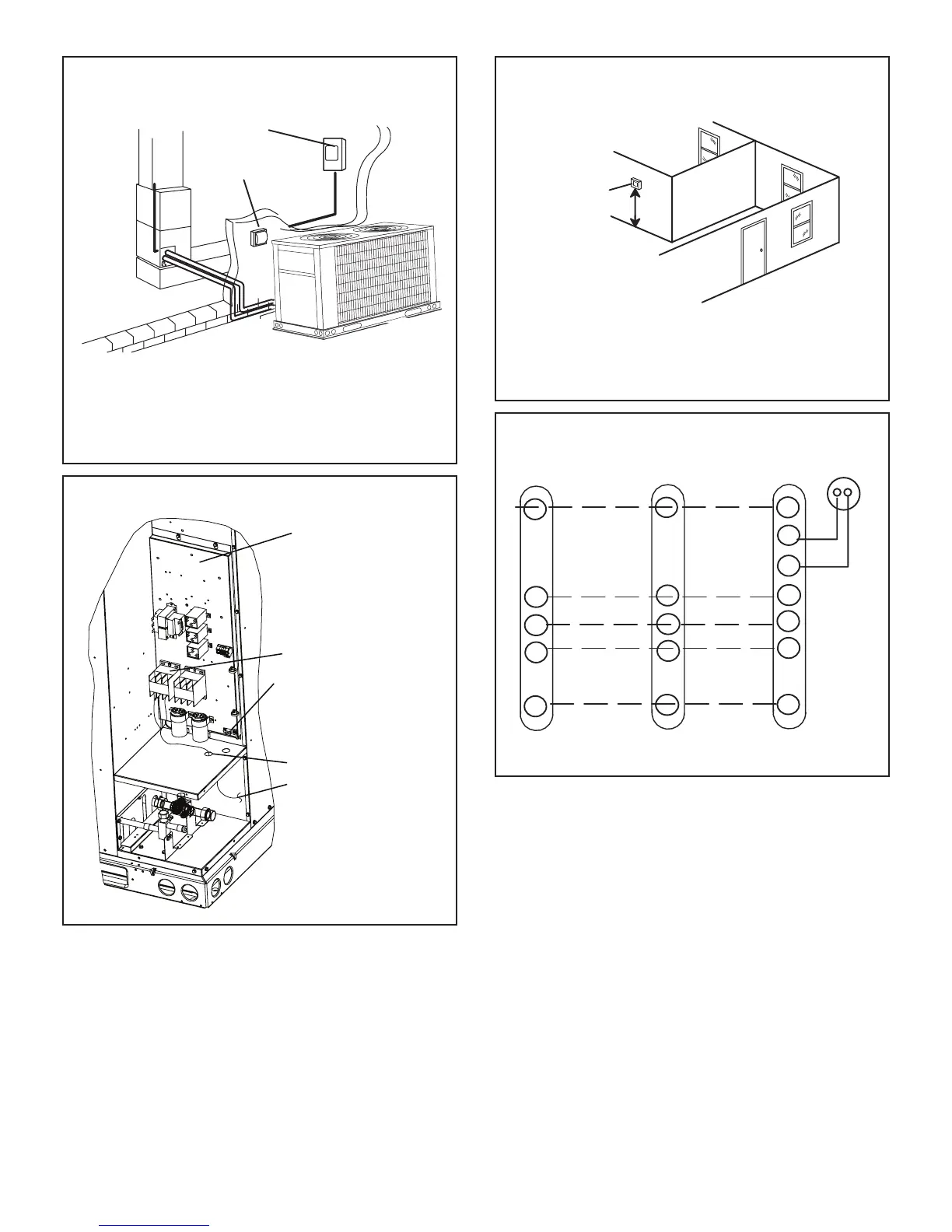
TYPICAL HIGH VOLTAGE POWER SUPPLY
CONNECTIONS
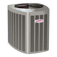
Install room thermostat (ordered separately) on an inside wall
approximately in the center of the conditioned area and 5 feet (1.5m)
from the floor. It should not be installed on an outside wall or where it
can be affected by sunlight, drafts or vibrations.
THERMOSTAT
5 FEET
(1.5M)
INSTALL THERMOSTAT
Install low voltage wiring from outdoor to indoor unit and from
thermostat to indoor unit as illustrated.
TYPICAL CONTROL WIRING
ELP HEAT
PUMP
C1
W1
C
R
C1
C
RO
ELA AIR
HANDER
Y1
C
R
A2
THERMOSTAT
RT2 REMOTE
SENSOR
S2
S1
W2
W
W2
W1
W2
 Loading...