Page 4
Model Number Identication
Brand/Family
Elite™ Product Line
P = Split System Heat Pump
Nominal Cooling Capacity -
Tons
090 = 7.5 Tons
120 = 10 Tons
Cooling Efficiency
S = Standard Efficiency
Minor Design Sequence
1 = 1st Revision
2 = 2nd Revision
3 = 3rd Revision
Voltage
Y = 208/230V‐3 phase‐60hz
G = 460V‐3 phase‐60hz
J = 575V‐3 phase‐60hz
M = 380/420V-3 phase-50hz
Refrigerant Type
4 = R-410A
Refrigerant Circuits
S = Single Circuit
Part Load Capability
N = Single Stage Compressor
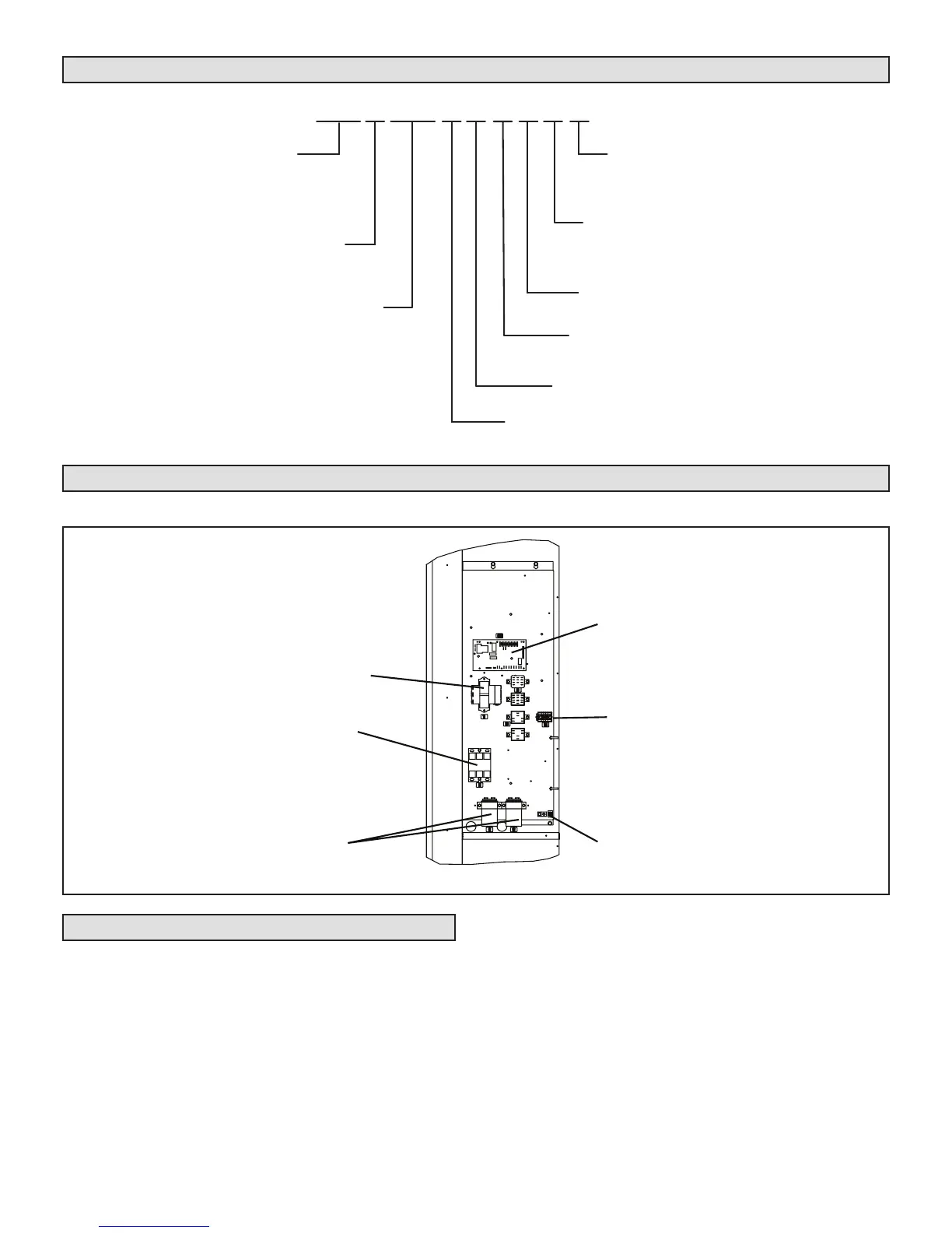
Unit Control Box Components Arrangement
ELP090S4S AND ELP120S4S
TRANSFORMER
(T1)
CONTACTOR
(K1)
RUN CAPACITORS
(C1, C2)
GROUND LUG
TERMINAL STRIP
(TB14)
DEFROST CONTRO
BOARD
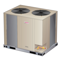
Rigging the Unit for Lifting
Rig the unit for lifting by attaching four cables to the holes
in the base rail of the unit. See gure 1.
1 - Remove protective packaging before rigging the
unit for lifting.
2 - Connect the rigging to the holes in each corner of
the unit’s base.
3 - All panels must be in place for rigging.
4 - Place a eld-provided H-style frame just above the
top edge of the unit. The frame must be of adequate
strength and length. (An H-style frame will prevent
the top of the unit from being damaged.)
 Loading...