Page 13
During a single thermostat cycle, the defrost control will
lock out the unit after the fth time that the circuit is in-
terrupted by any pressure switch that is wired to the con-
trol board. In addition, the diagnostic LEDs will indicate
a pressure switch lockout after the fth occurrence of an
open pressure switch (table 7). The unit will remain locked
out until power is broken then remade to the control or un-
til the jumper is applied to the TEST pins for 0.5 seconds.
NOTE – The defrost control board ignores input from the
loss-of-charge switch terminals during the TEST mode,
during the defrost cycle, during the 90-second start-up
period, and for the rst 90 seconds each time the revers-
ing valve switches heat/cool modes. If the TEST pins are
jumpered and the 5-minute delay is being bypassed,
the LO PS terminal signal is not ignored during the
90-second start-up period.
SERVICE LIGHT CONNECTION
The defrost control board includes terminal connections
for a service light which provides a signal that activates
the room thermostat service light during periods of inef-
cient operation.
IMPORTANT
After testing has been completed, properly reposition
test jumper across desired timing pins.
DIAGNOSTIC LEDS
The defrost board uses two LEDs for diagnostics. The
LEDs ash a specic sequence according to the diagno-
sis (table 7).
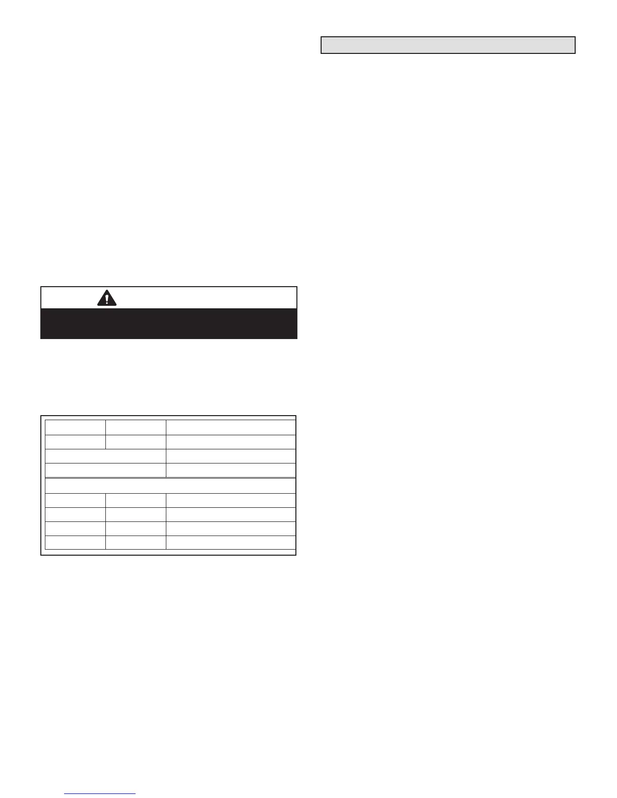
TABLE 7. Defrost Control Board Diagnostic LEDs
DS2 Green DS1 Red Condition
OFF OFF Power problem
Simultaneous Slow Flash Normal operation
Alternating Slow Flash 5-min. anti-short cycle delay
Fault and Lockout Codes
OFF Slow Flash Loss-of-Charge Fault
OFF ON Loss-of-Charge Lockout
Slow Flash OFF High Pressure Fault
ON OFF High Pressure Lockout
Maintenance
At the beginning of each cooling season, the system
should be checked as follows:
OUTDOOR UNIT
1 - Clean and inspect the condenser coil. You can ush
the coil with a water hose.
2 - The outdoor fan motor is prelubricated and sealed.
No further lubrication is necessary.
3 - Visually inspect connecting lines and coils for
evidence of oil leaks.
4 - Check wiring for loose connections.
5 - Check for correct voltage at the unit while the unit is
operating and while it is off.
6 - Check amp-draw of the outdoor fan motor.
Unit nameplate _________ Actual ____________
7 - Check amp-draw of the compressor.
Unit nameplate _________ Actual ____________
NOTE — If the owner complains of insufcient cooling,
gauge the unit and check the refrigerant charge. Refer to
section on refrigerant charging in this instruction.
INDOOR COIL
1 - If necessary, clean the coil.
2 - Check connecting lines and coils for evidence of oil
leaks.
3 - If necessary, check the condensate line and clean it.
INDOOR UNIT
1 - Clean or change lters.
2 - Adjust the blower speed for cooling. Measure the
pressure drop over the coil to determine the correct
blower CFM. Refer to the unit information service
manual for pressure drop tables and procedure.
3 - On belt drive blowers, check the belt for wear and
proper tension.
4 - Check all wiring for loose connections.
5 - Check for correct voltage at the unit (blower
operating).
6 - Check amp-draw on blower motor.
Unit nameplate _________ Actual ____________
 Loading...