Page 19
I - UNIT COMPONENTS
A − Variable Frequency Drive A96
Air handler units are equipped with a VFD which alters
the supply power frequency and voltage to the blower mo-
tor. Blower speed is staged depending on the compres-
sor stages, heating demand, or ventilation demand. The
amount of airow for each stage is preset from the factory.
The VFD is located below the VFD Control Board.
B − Economizer Relay K43
Relay K43 is a single−pole double throw relay used to
control the economizer. When there is a call for cooling,
K43−1 contacts close energizing the economizer. See wir-
ing diagram.
C − Blower Motor B3
See page 10 for blower drive specications and blower
motor electrical data.
D − Terminal Block TB1
All eld wring connections are made at terminal block TB1.
E-Terminal Block TB13
VFD line voltage connections are made to TB13 located
in the control box.
F − Condensate Pan and Over Flow Relay K220 and
Switch S149
A reversible drain pan is provided. Never connect conden-
sate drain to a closed system. Condensate drain line must
have a trap in the line at the unit exit. K220 and S149 are
eld installed and used to prevent condensate overow.
In the event of a blocked drain plug and condensate be-
gins rise, N.O. S149 will close energizing relay K220. N.C.
K220 opens de−energizing the the unit.
G – Freezestats S49, S50
Each unit is equipped with a low temperature switch
(freezestat) located on the evaporator coil; S49 (rst cir-
cuit), S50 (second circuit), on the corresponding evapora-
tor coils.
The freezestats are connected in parallel to each other
on one dual-stage compressor unit and in series on two
dual-stage compressor units. Each freezestat is a SPST
N.C. auto-reset switch which opens at 29°F ± 3°F (-1.7°C
± 1.7°C) on a temperature drop and closes at 58°F ± 4°F
(14.4°C ± 2.2°C) on a temperature rise. To prevent coil ic-
ing, freezestats open during compressor operation to tem-
porarily disable the respective compressor until the coil
warms suciently to melt any accumulated frost.
If the freezestats are tripping frequently due to coil icing,
check the unit charge, airow and lters before allowing
unit back in operation. Make sure to eliminate conditions
which might promote evaporator ice buildup.
H – Inverter Protection Relay K232
Inverter Protection Relay K232 is DPDT with 24V Coil.
N.O K232-1 closes to energize inverter A96. If the inverter
trips, K232-1 opens to de-energize inverter A96.
I – VFD Control Board A183
VFD control board A183 is a solid-state control board
powered with 24VDC from the variable frequency drive
A96. A183 gets signals from the thermostat to determine
blower speeds For more information on the A183, refer to
the MSAV Start Up section. Control A183 is located above
the VFD.
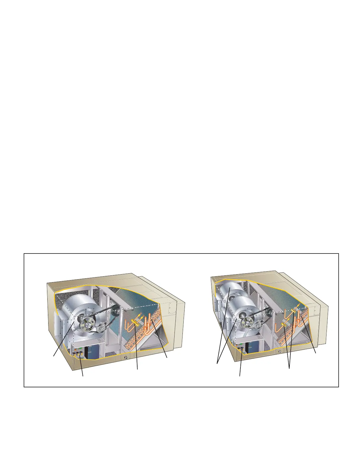
072/090/120/150 180/240
Control BoxControl Box
Blower
Blowers
Expansion Valve
Expansion Valve
Coil
Coil
FIGURE 1. Unit Components

 Loading...

