Page 21
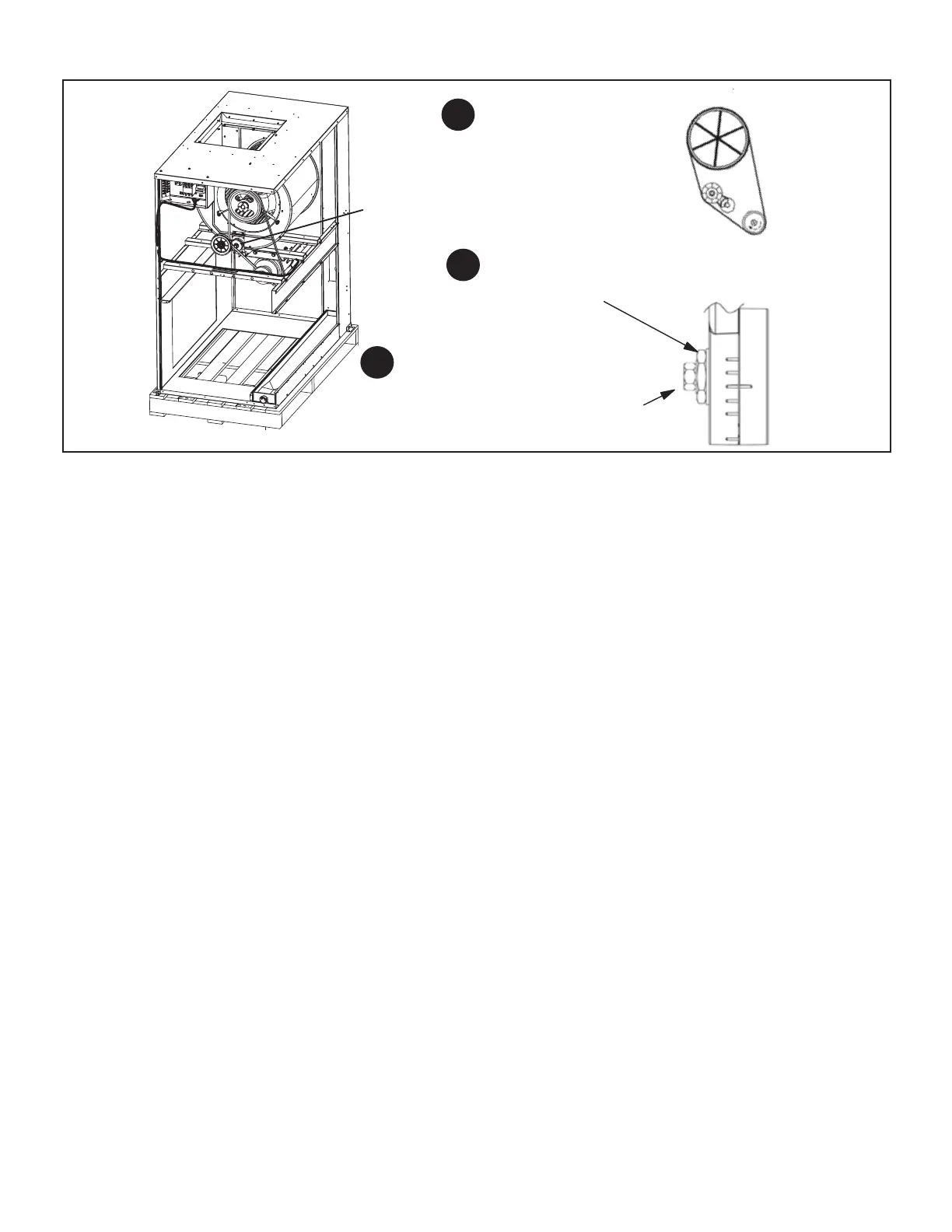
Adjusting Belt Tension
Place belt over all three pulleys.
Using a 15/16" wrench on the
tensioner body nut, apply force until
marks align as shown.
While holding the tensioner in this position,
tighten the mounting bolt to 23 ft−lbs using
a 9/16" wrench.
1
2
3
BELT TENSIONER
FIGURE 4
IV − Electric Heat Components
See electric heat tables (table of contents) for electric heat
matchups. T3EH- units consists of electric heating ele-
ments exposed to the air stream. Multiple−stage elements
are sequenced on and o by time delays in response to
thermostat demand.
1 − Heating Elements HE1, HE2, HE3 and HE4
Heating elements are composed of helix wound bare ni-
chrome exposed directly to the air stream. Heating ele-
ments are energized directly by contactors. Once ener-
gized, heat transfer is instantaneous. Over temperature
protection is provided by primary and secondary high tem-
perature limits. Overcurrent protection is provided by fuses.
Each stage of electric heat consists of three elements con-
nected in a three-phase arrangement. Elements in 208/230V
units are connected in a “Delta” arrangement. Elements in
460 and 575V units are connected in a “Wye” arrangement.
Each stage is energized independently by a three-pole dou-
ble-break contactor and is protected by safety limits.
2 − Contactors K15 and K16
Contactors K15 and K16 are three−pole double break re-
lays with a 24 volt coil that energize their respective heating
elements on thermostat demand. K15 energizes rst stage
heat elements and K16 energizes second stage elements.
3 − Electric Heat Sequencer Relays K32
Relay K32 is a N.O. sequencer relay with a resistive ele-
ment for a coil and a bi-metal disk which actuates the con-
tacts. The relays are located on the electric heat vestibule
panel and are energized by a 24V heating demand (W1,
W2). When energized, the internal resistance heats the
bi-metal disk causing the contacts to close. When the re-
lay is de-energized, the disk cools and the contacts open.
The relay energizes dierent stages of heat.
4 − Relays K9 and K19
Relays K9 and K19 are used to electrically isolate the
ELXA 24 volts components from the T3EH- 24 volt com-
ponents. The coil on the relays are connected to rst stage
and second stage heat. On a rst stage heat demand K9
is energized. K9−1 closes energizing rst stage heat con-
tactor K15. On a second stage heat call K19 is energized.
When K19−1 closes contactor K16 is energized which en-
ergizes relay K32.
5 − Fuse F3
Heating elements in all T3EH- units are protected by fuse F3.
The fuse is connected in series with each leg of electric heat.
6 − Fuse F4
F4 serves the same purpose as F3 but is in line with line
voltage and protects the indoor blower.
7 − Transformer T2
T2 is line voltage to 24VAC which provides 24VAC to pow-
er to all T3EH- contactor coils, relays and timers.
8 − High Temperature Limit S15 (Primary)
S15 is the primary high temperature limit. It is located in
the electric heat unit immediately downstream from the
heating elements. S15 is a single-pole single-throw nor-
mally closed thermostat wired in series with the rst stage
contactor coil.
When S15 opens, indicating a problem in the system, con-
tactor K15 is de-energized. When K15 is de-energized, rst
stage and all subsequent stages of heat are de-energized.
Since the indoor blower is controlled by thermostat demand
(K9 remains energized), the indoor blower continues oper-
ating.
9 − High Temperature Limit S20 (Secondary)
Each heating element assembly is electrically connected
to two high temperature limits S20 (refer to wiring dia-
grams in back of this manual). Each limit is connected in
series with one leg of the three-phase element assembly.
The third leg of each assembly is not equipped with a lim-
it. Three-phase operating characteristics allow one of the
other two limits to protect the third leg.

 Loading...

