Page 20
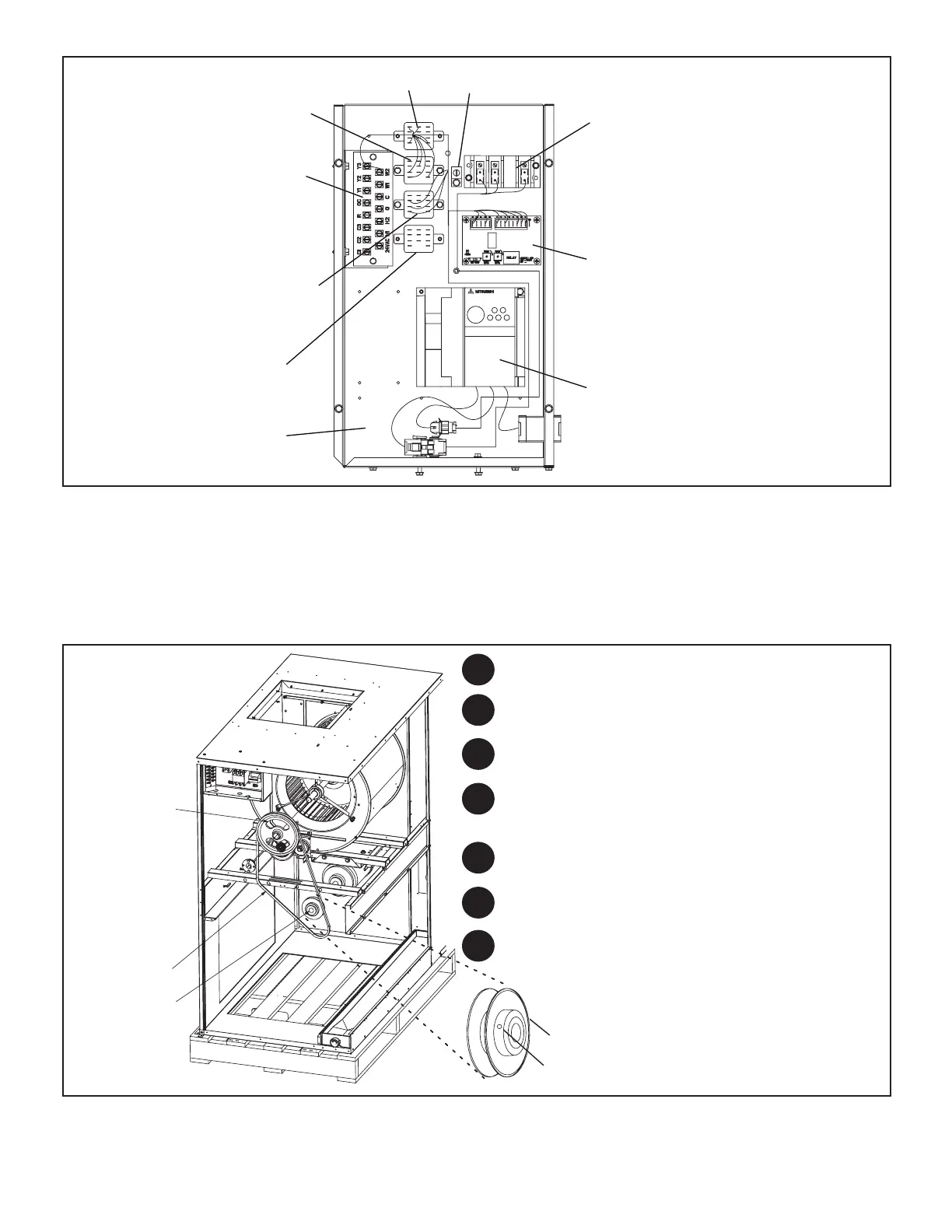
CONTROL
PANEL
K220 RELAY
(FIELD INSTALLED)
MSAV RELAY
(K232)
TERMINAL STRIP
(TB1)
TERMINAL BLOCK
(TB13)
INVERTER
(A96)
MSAV CONTROL BOARD
(A183)
BLOWER SPEED SWITCHING
RELAY (K264)
BLOWER RELAY
(K43)
GROUND LUG
FIGURE 2. Unit Control Box Arrangement
II − REFRIGERATION SYSTEM
Units are equipped with single refrigerant circuit (072) or dual refrigerant circuit (090−240). The 090−240 units have a dual
distribution system for two stage capacity control during cooling cycles. Each circuit has its own service valve connection
and expansion valve.
III − BLOWER SPEED & BELT TENSION
Air Volume Adjustment
FIXED PULLEY
BLOWER BELT
ADJUSTABLE
PULLEY
ADJUSTABLE PULLEY
ALLEN SCREW
Run the blower without a cooling demand.
Use the static pressure and rev/min readings to
determine the unit’s air volume (see applicable blower
performance tables).
Measure the indoor blower motor’s rpm.
Measure the static pressure external to the unit.
NOTE − The indoor coil must be dry and the air
filters must be in place when the following
measurements are taken.
Loosen the Allen screw on the adjustable pulley.
Turn the adjustable sheave clockwise to increase the air
volume or counterclockwise to decrease the air volume.
Once the desired air volume has been achieved, tighten
the Allen screw.
1
2
3
4
5
6
7
FIGURE 3

 Loading...

