Page 23
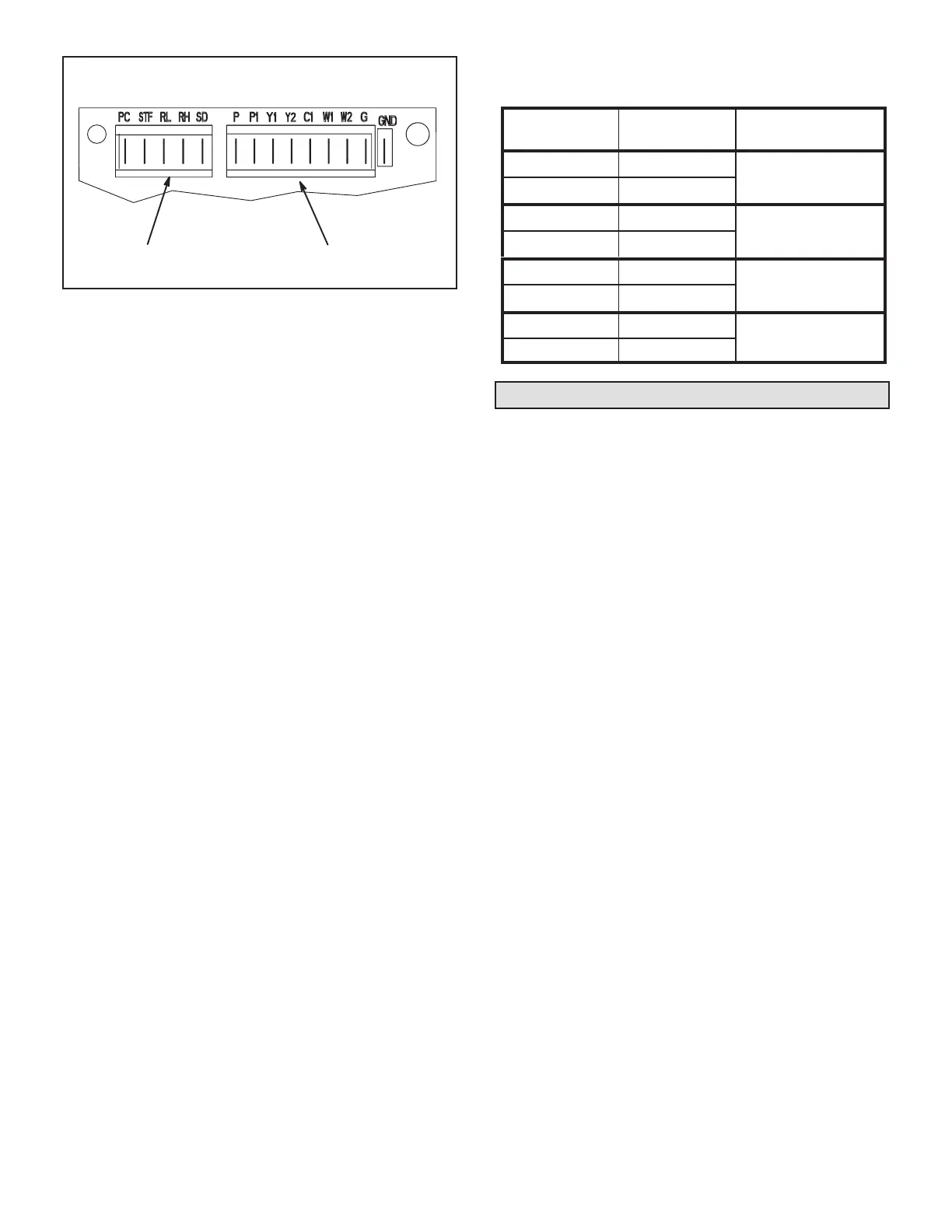
LVC2 BOARD TERMINAL DESIGNATIONS
24VAC
THERMOSTAT INPUTS;
24VDC
VFD INPUTS;
FIGURE 6
4 - If there is no thermostat signal, troubleshoot back
toward the thermostat.
5 - Check the power LED on the board. See gure 17.
6 - If the power LED is not on, check voltage between
LVC2 terminals PC (H2-1) and SD (H2-5). Voltage
should read 24VDC.
7 - If voltage does not read 24VDC, disconnect the H2
header from the LVC2 VFD inputs terminal block (to
make sure the LVC2 is not shorting 24VDC supply
from the inverter). Measure the voltage between
the end terminals on the H2 header. If 24VDC is
present, replace the LVC2 board. If no voltage is
read, troubleshoot the VFD.
8 - When LVC2 24VAC thermostat blower (G) input and
24VDC power are present, check the LVC2 low and
high speed outputs. The LVC2 uses inverse logic to
enable the blower; 1VDC will be read at the enabled
blower speed terminal. See table 3.
9 - If all inputs are correct and the unit still does not
operate as intended, replace LVC2 board.
TABLE 1
LVC2 BOARD BLOWER OUTPUTS
Output
Terminals
Voltage Blower Operation
RL-SD 1VDC
Low Speed
RH-SD 24VDC
RL-SD 24VDC
High Speed
RH-SD 1VDC
RL-SD 1VDC
Illegal State
(replace board)
RH-SD 1VDC
RL-SD 24VDC
Blower Off
(replace board)
RH-SD 24VDC
Verify Proper Operation
If the blower is not rotating in the proper direction:
1 - Disconnect all power to the unit and open the
compressor / controls compartment access panel.
2 - Reverse any two power wires going from the VFD
to the blower motor.
3 - Check all wiring to the VFD. No wires should be
connected to TB2-STR.
4 - Check to ensure that wiring connections are secure.
5 - Close access panel and restore power to unit.
Verify proper operation of VFD:
Refer to supply air inverter start-up instructions above.
NOTE – Operate unit in the heating mode or mode which
operates at the highest blower speed. Measure amp draw
to blower motor between the VFD and blower motor. Veri-
fy that the amperage does not exceed the FLA value listed
on the motor nameplate.

 Loading...

