Page 42 - IOM / ROOF-TOP FLEXY™ Series
USING THE KP07 GRUSING THE KP07 GR
USING THE KP07 GRUSING THE KP07 GR
USING THE KP07 GR
APHIC CONTROL DISPLAAPHIC CONTROL DISPLA
APHIC CONTROL DISPLAAPHIC CONTROL DISPLA
APHIC CONTROL DISPLA
YY
YY
Y
This display unit allows you to operate 1 to 8 machines.
The icon and schematic display provides a vivid and
user-friendly interface.It uses a liquid crystal
monochrome display, with background lighting,
consisting of 240 x 128 pixels. It has 2 LEDs and 12
keys.
The remote console must be connected to the unit
using a 4 x 0.5 mm² braid-screened cable. (maxi lenght
is 1000 m maxi).
Plan the console electric supply in 230V/50Hz (500 mA)
On the unit, connection the the KP01 card J18 input
will be done with connection items (screws...) delivered
with the console.
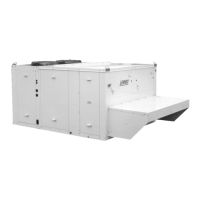
ITEMS:
1 LCD SCREEN, 240x128 PIXELS, MONO-
CHROME, BACKGROUND LIGHTING
2 5 KEYS FOR FIXED FUNCTIONS
3 7 "SCREEN" KEYS FOR VARIOUS
FUNCTIONS
4 "ON" LED
5 "GENERAL ALARM" LED.
The main display unit functions are as follows:
- Control of a range of interactive screens allowing
access to all information and control data.
- Continual resetting of all dynamic parameters
displayed in the various screens.
- Recording of successive status of pre-defined
variables to create analog and event histories.
A KP07 unit can be attached to more than 8 Lennod
Rooftops, providing they have the same software.
The link between the controllers and the display is serial
and uses the JBUS protocol. After being connected,
the unit tries to establish communication with the
specified machines. If, after 3 attempts, the unit cannot
communicate with the Roof-Top(s), the latter will be
"disconnected". The connection failure is displayed on
the screen and recorded in the event history. The
display unit will then try to re-connect at regular
intervals.
NOTE : To adjust the screen contrast, please consult
the end of this part.
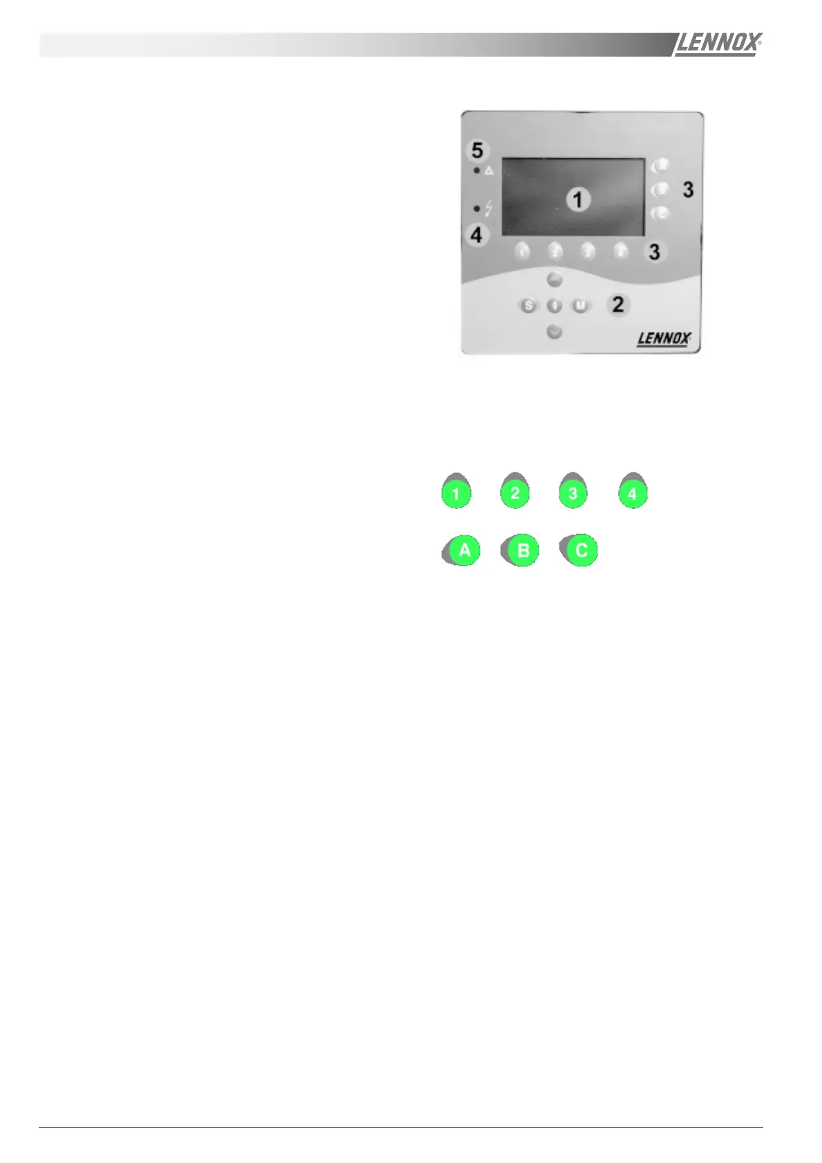
1 - SCREEN KEYS WITH VARIABLE
FUNCTIONS (Figure 41)
There are 7 keys located around the LCD screen :
The function of these keys may vary from one screen
to another and is defined on the active screen by an
icon. In the case of keys [1], [2], [3] and [4], the icon is
displayed above the key. For the 3 other keys [A], [B]
and [C], the icon appears to their left.
Each key allows you to:
- Proceed to another screen, or
- Write a value in a given variable.
Figure 41
 Loading...