Page 6 - IOM / ROOF-TOP FLEXY™ Series
PRELIMINARY CHECK
Before installing the equipment, the following items
MUST be checked:
- Is there sufficient space for the equipment?
- Is the surface on which the equipment will be
placed sufficiently solid to withstand its weight? A
detailed study of the frame must be made
beforehand.
- Do the supply and return ductwork openings
excessively weaken the structure?
- Are there any obstructing items which could
hinder the operation of the equipment?
- Does the electrical power available correspond to
the equipment's electrical specifications?
- Does the noise level of the equipment meet the
specification ?
- Is drainage provided for the condensate?
- Is there sufficient access for maintenance?
- Installation of the equipment could require
different lifting methods which may vary with
each installation (helicopter or crane). Have these
been evaluated ?
In general, make sure no obstacles (walls, trees or roof
ledges) are obstructing the duct connections or
hindering assembly and maintenance access.
INSINS
INSINS
INS
TT
TT
T
ALLAALLA
ALLAALLA
ALLA
TIONTION
TIONTION
TION
CONNECTIONS DEVICE
- Ensure that all the pipework crossing walls or
roofs are insulated and secure.
- To avoid condensation problems, be sure all
pipes are insulated according to temperatures of
fluids and type of rooms.
NOTE : The AQUILUX covers which protect the finned
surfaces must be removed prior to unit commissioning.
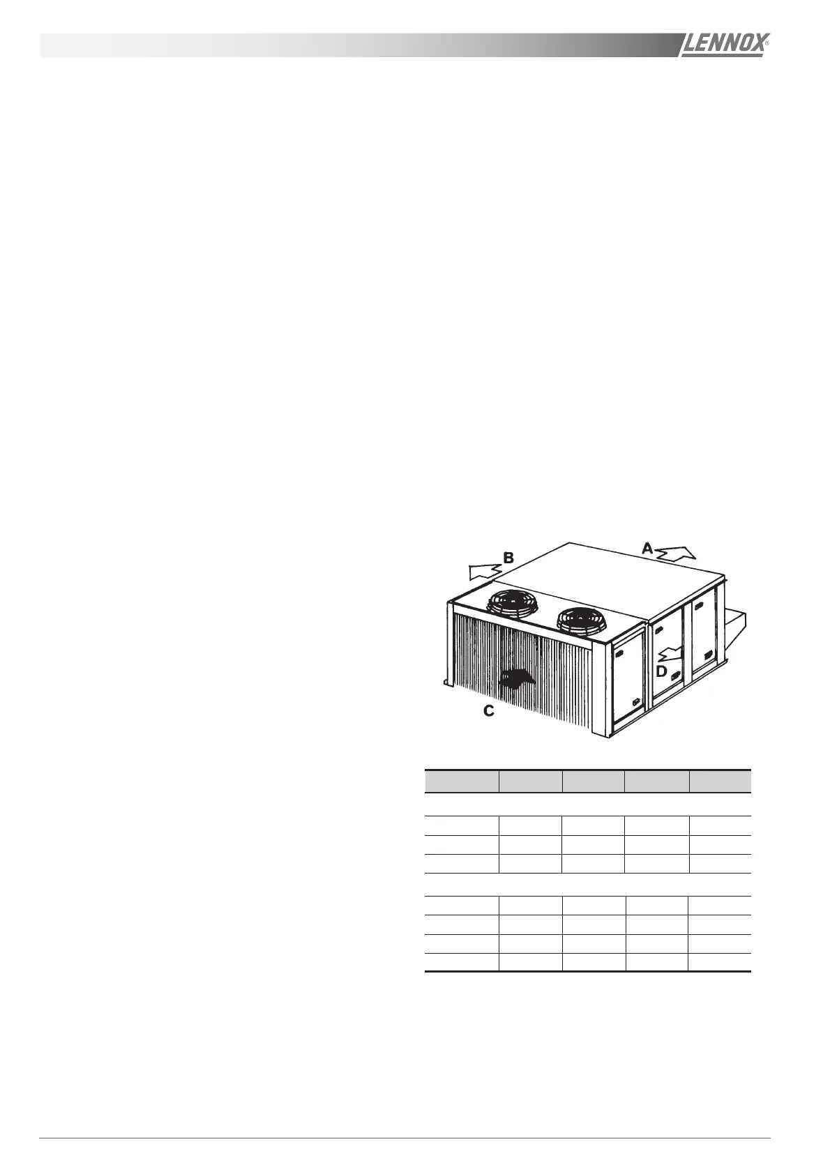
Figure 4
MODELS ABCD
FC/FH/FG/FD
50 1000 1000 1000 2000
60 è 140 1400 1000 1400 2300
160 & 190 2000 1000 2000 2300
FX
25 & 30 * 1100 * 1700
35 è 55 * 1300 * 2300
70 è 100 * 1700 * 2300
110 è 170 * 2000 * 2300
* : according to connection
INSTALLATION DEVICE
The surface on which the equipment is to be installed
must be clean and free of any obstacles which could
hinder the flow of air to the condensers:
- Avoid uneven surfaces
- Avoid installing two units side by side or close to
each other as this may restrict the airflow to the
condensers.
Before installing a packaged rooftop unit it is important
to understand:-
- The direction and position of air flows.
- The external dimensions of the unit and the
dimensions of the supply and return air connec-
tions.
- The arrangement of the doors and the space
required to open them to access the various
components.
Figure 4 shows the required clearances and
dimensions.
 Loading...