Page 18
IMPORTANT
24 VAC half wave rectified (DC pulse), when mea
sured with a meter, may appear as a lower or high
er voltage depending on the make of the meter.
Rather than attempting to measure the output
voltage of A24, see G21V/GSR21V V" BLOWER
AND VSP2 BLOWER CONTROL BOARD TROU
BLESHOOTING FLOW CHART in the TROUBLE
SHOOTING section of this manual.
Diagnostic LED Lights
1 − DS3 ON/OFF"
ON/OFF−DS3 indicates there is a demand for the blower
motor to run. When the ON/OFF LED−DS3 is lit, a demand
is being sent to the motor. In heating mode only, there is a
45 second fan ON" delay in energizing ON/OFF LED−DS3.
The light will not go off until adjustable fan OFF" delay has
expired.
If ON/OFF LED−DS3 is on and both HIGH/LOW LED−
DS1 & HEAT LED−DS2 are off, the motor will operate in
low speed.
a − DS2 HEAT"
If HEAT LED−DS2 is on, the blower is running in the heat
speed according to the HEAT" jumper setting. In heating
mode only, there is a 45 second delay in energizing HEAT
LED−DS2. Light will not go off until adjustable fan OFF"
delay has expired.
b − DS1 HI/LOW"
HIGH/LOW LED−DS1 indicates whether the blower is op
erating in high or low speed. When the light is off, the blow
er is running in low speed according to the LOW" jumper
setting. When HIGH/LOW LED−DS1 is on, the blower is op
erating in high speed according to the HIGH" jumper set
ting.
c − DS4 CFM"
CFM LED−DS4 indicates the CFM the unit is operating,
according to the jumper settings. The light flashes once
for approximately every 100 CFM. For example, if the unit
is operating at 1000 CFM, CFM LED−DS4 will flash 10
times. If the CFM is 2050, CFM LED−DS4 will flash 20 full
times plus one fast or half flash.
At times the light may appear to flicker or glow. This takes
place when the control is communicating with the motor be
tween cycles. This is normal operation.
The appropriate speed according to application and CFM
need is selected by moving jumper pins.
NOTE−On Harmony II zoning applications in the heating
mode, the highest speed obtainable is the same as the highest
cooling speed selection. Also, the heating speed (heat jumper
position) is only used when the primary limit has been tripped.
In non−zoning applications, refer to the section on the VSP2−1
control.
Jumper Settings
IMPORTANT
Before changing jumper setting, make sure the
motor has completely stopped. Any jumper set
ting change will not take place while the motor is
running.
To change jumper positions, gently pull the jumper off the pins
and place it on the desired set of pins. The following section
outlines the different jumper selections available and con
ditions associated with each one. Refer to figure 13 for
identification.
After the CFM for each application has been determined,
the jumper settings must be adjusted to reflect those given
in the tables on pages 7 and 8. Using the tables, determine
which row of CFM volumes most closely matches the de
sired CFM. Once a specific row has been chosen (+, NOR
MAL, or −), CFM volumes from other rows cannot be used.
Below are the descriptions of each of the jumper selec
tions.
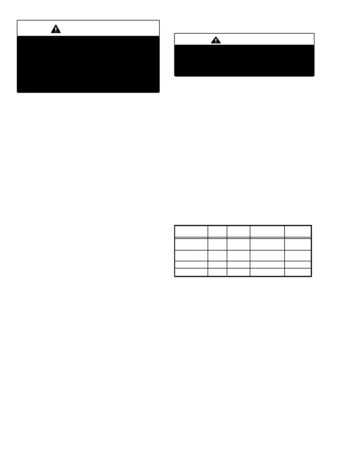
Refer to table 4 for factory settings. Refer to the tables on
pages 7 and 8 for the approximate air volume for each set
ting.
TABLE 4
MODEL
NUMBER
G21V5−80
G21V3−60
G21V5−100
G21V3−80
VSP2−1 FACTORY SETTINGS
HIGH LOW HEA
T
141
241
ADJUST
NORM
NORM
GSR21V5−80
141
241
NORM
NORM
GSR21V5−100
a−ADJUST"
The ADJUST pins allow the motor to run at normal speed,
approximately 10% higher, or approximately 10% lower than
normal speed. The tables on pages 7 and 8 give three rows (
+, NORMAL, and −) with their respective CFM volumes. No
tice that the normal adjustment setting for heat speed position
#3 in the G21V5−80/100 blower data table is 2080 CFM. The
+ adjustment setting for that position is 2270 CFM and for the
− adjustment setting is 1860 CFM. After the adjustment set
ting has been determined, chose the remainder speed jump
er settings from those offered in the table.
The TEST pin is available to bypass the VSP2−1 control
and run the motor at approximately 70% to test that the mo
tor is operational. This is beneficial primarily in trouble
shooting. G must be energized for motor to run.
 Loading...