Page 24
ÉÉÉÉÉÉÉÉÉÉÉÉÉÉÉ
ÉÉÉÉÉÉÉÉÉÉÉÉÉÉÉ
THERMOSTAT DEMAND
PURGE BLOWER
GAS VALVE
IGNITION SPARK
0
30
ON
OFF
1
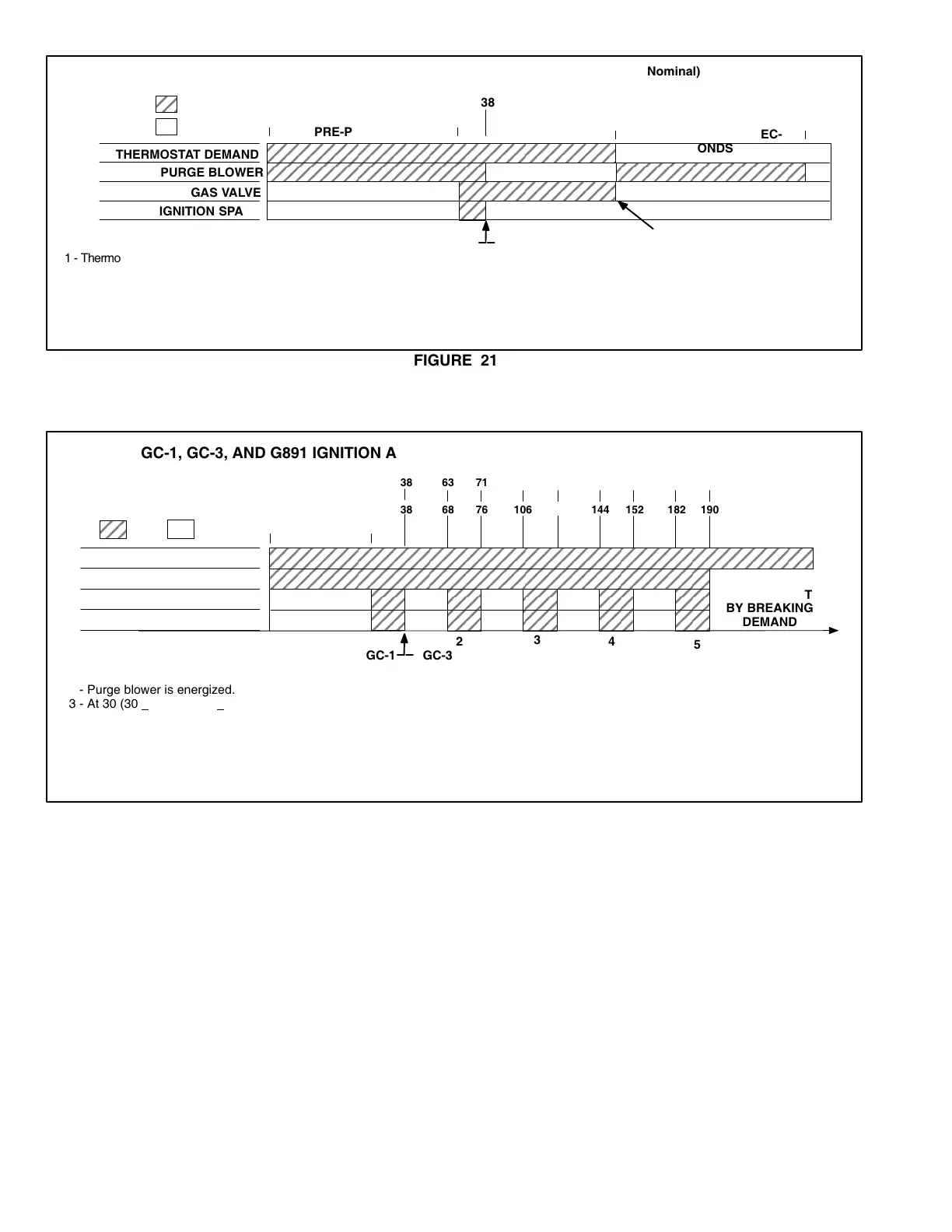
GC1, GC3, and G891 NORMAL IGNITION SEQUENCE
IGNITION TRIAL
END OF HEATING DEMAND
POSTPURGE 30 SEC
ONDS
FIGURE 21
38
PREPURGE 30 SEC.
GC1 GC3
GC3GC1
(Timings Nominal)
1 − Thermostat demand for heat.
2 − Purge blower is energized.
3 − At 30 seconds gas valve and ignition spark are energized for
eight seconds.
4 − When ignition occurs (sensed by flame rectification), the
spark and purge blower remain energized for the remainder
of the 8.0 seconds (GC1, G891, and later GC3 controls with part
numbers 97H02 and 52J18). Early GC3 controls, with part
number 72H68 deenergizes spark and purge .5 seconds after
flame is sensed or after 8.0 seconds if flame is not sensed.
5 − At end of heating demand, gas valve is deenergized and purge
blower is started.
6 − Post purge continues for 30 seconds after heating cycle, then
is deenergized.
ÉÉÉÉÉÉÉÉÉÉÉÉÉÉÉÉÉÉÉÉÉÉÉÉ
ÉÉÉÉÉÉÉÉÉÉÉÉÉÉÉÉÉÉÉÉÉÉÉÉ
THERMOSTAT DEMAND
PURGE BLOWER
GAS VALVE
IGNITION SPARK
0
30
ON
OFF
1
ÉÉÉÉÉÉÉÉÉÉÉÉÉÉÉÉÉÉÉ
ÉÉÉÉÉÉÉÉÉÉÉÉÉÉÉÉÉÉÉ
IGNITION TRIAL
RESET AT
THERMOSTAT
BY BREAKING
DEMAND
38
38
GC3GC1
2
3
4
5
68 76 106 144 152 182 190
63 71
GC1, GC3, AND G891 IGNITION ATTEMPT SEQUENCE FOR RETRIALS
1 − Thermostat demand for heat.
2 − Purge blower is energized.
3 − At 30 (30 + 2 GC1, 30 + 5 GC3 and G891) seconds gas valve
and ignition spark are energized for 8 seconds.
4 − If no ignition is sensed, purge blower continues to run.
5 − After additional 30 seconds (GC1 and G891) (25 seconds
GC3), ignition retrial takes place for another 8 seconds.
6 − If no ignition is sensed, purge blower continues to run for
another 30 seconds (GC1 and G891) (25 seconds GC3).
7 − This sequence is repeated for five trials; without ignition the
control locks out until reset at the thermostat.
8 − With ignition occurring at any trial, the ignition spark and
purge blower remain energized for the duration of that trial
(GC1, G891, and later GC3 controls with part numbers
97H02 and 52J18) or are deenergized after .5 seconds if
flame is sensed (Early GC3 with part number 72H68).
96 104
114
129 137 162 170
GC1 / G891 TIMINGS (SEC.)
GC3 TIMINGS (SEC.)
(Specific Timings)
FIGURE 22
G − Gas Valve and Expansion Tank
(Figure 23)
1 − Gas Valve
Gas valves used on G21/GSR21 series units have vari
ous opening times. All gas valves are internally redun
dant to assure safety shutoff. If replacement is neces
sary, the valve must be replaced with the same type of
valve. For example, replace a White Rodgers as shown
in figure 23 with a White Rodgers valve.
2 − Expansion Tank
An expansion tank downstream of the gas valve ab
sorbs back pressure created during combustion to pre
vent damage to gas valve diaphragm.
3 − Gas Valve Conversion (Figure 24)
A gas changeover kit is available to convert A.G.A. / C.G.A.
natural gas units to LP gas. Refer to the instructions provided
in each specific kit for proper installation procedures.
A.G.A. / C.G.A. GSR21 (50,80) units are shipped with the
components required for field conversion to LP gas.
 Loading...