Page 23
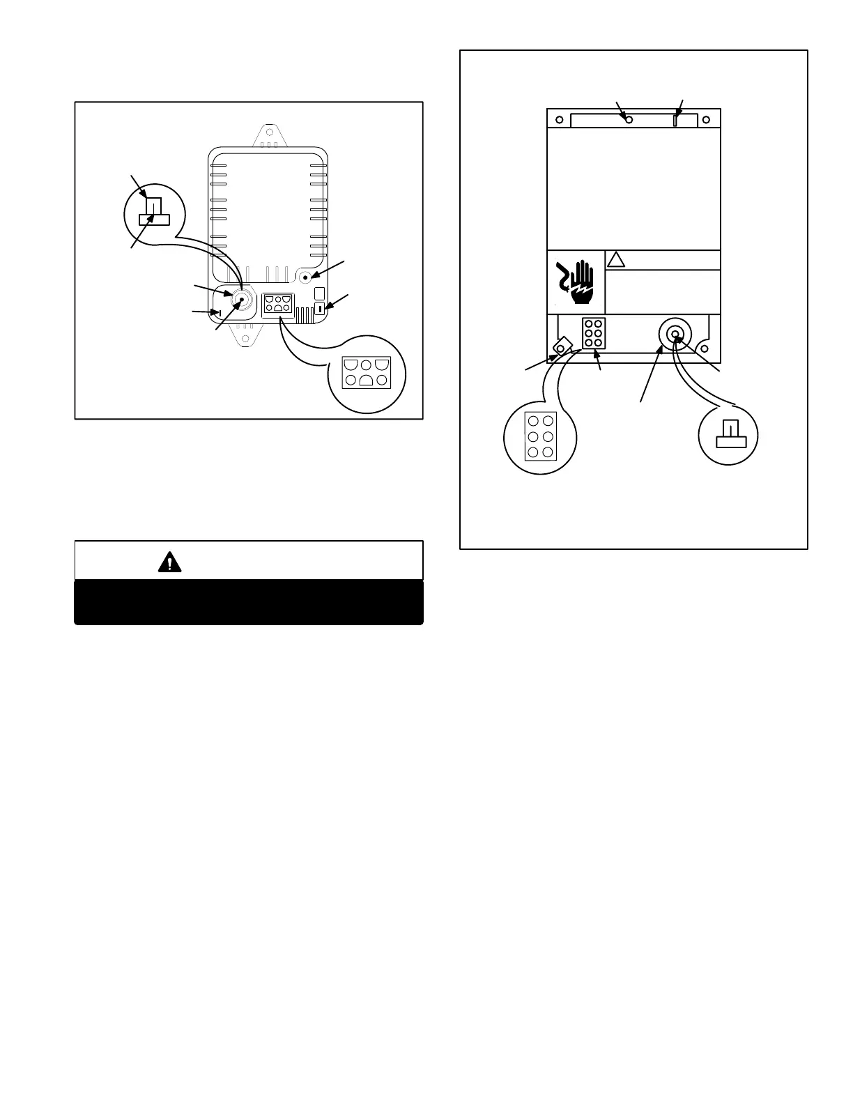
Spark wire connection is made to a barbed nail type con
nector on the control. Sensor wire connection is made to a
3/16" quick connect terminal opposite the barbed nail.
GREEN
LED
123
456
NEUTRAL
SENSE
TERMINAL
BARBED NAIL
CONNECTOR
TRANSFORMER
GC3 IGNITION CONTROL
1 24 VAC FROM TSTAT W"
2 COMMON
3 24 VAC TO GAS VALVE
4 24 VAC INPUT FROM TRANSFORMER T1
5 120 VAC TO PURGE BLOWER
6 120 VAC INPUT
TO REMOVE WIRE:
GRASP WIRE WITH
FINGERS AND PULL
STRAIGHT OUT
BARBED NAIL
CONNECTOR
J72
CONNECTOR
FIGURE 19
Three models of the GC3 were made, early model
(72H68−white cover) and later models (97H02−white cover
and 52J18−green cover). The early model GC3 stops
spark as soon as a suitable flame is sensed, while the later
model energizes the spark for a full eight seconds.
IMPORTANT
A ceramic resistor spark plug must be used with
Lennox ignition controls.
3 − Johnson G891 Ignition Control (Figure 20)
The Johnson G891 ignition control (A3) has a blue plastic
cover, and is illustrated in figure 20. The unit wiring harness
(P72) plugs directly into the jack (J72) at the bottom of the
control. A diagnostic indicator light, a green LED, is located
on the top center of the control, near the sense terminal.
Spark wire connection is made to a barbed nail type con
nector on the control. Sensor wire connection is made to a
3/16" quick connect terminal opposite the barbed nail.
Like the later GC3 controls the G891 energizes the spark
for a full eight seconds.
GREEN
LED
1
2
3
4
5
6
NEUTRAL
SENSE
TERMINAL
BARBED
NAIL
CONNECTOR
TRANSFORMER
G891 IGNITION CONTROL
BARBED
NAIL
CONNECTOR
J72
CONNECTOR
FIGURE 20
!
1 24 VAC FROM TSTAT W"
2 COMMON
3 24 VAC TO GAS VALVE
4 24 VAC INPUT FROM TRANSFORMER T1
5 120 VAC TO PURGE BLOWER
6 120 VAC INPUT
4 − Ignition Control Functions For GC1, GC3,
and G891 (Figures 21 and 22)
The ignition control (A3) provides four main functions: pre
purge, ignition, flame sensing and postpurge. The ignition at
tempt sequence of the control provides five trials for ignition
before lock out. See figure 21 for normal ignition sequence
with nominal timings for simplicity.
Proper gas/air mixture is required for ignition on the first at
tempt. If there is slight deviation, within tolerance of the unit, a
second or third trial may be necessary for ignition.
The control will lock out the system if ignition is not obtained
within five trials. Reset after lockout requires only breaking and
remaking the thermostat demand. Watchguard will automati
cally reattempt ignition after one hour if there is still a thermo
stat heating demand. See figure 22 for the ignition attempt se
quence for retrials (nominal timings given for simplicity). Loss
of combustion during a heating cycle is sensed through ab
sence of flame signal causing the control to deenergize the
gas valve and repeat the ignition sequence if a thermostat
heating demand is present.
Ignition control timings (timing specific) are given in fig
ure 22.
 Loading...