Page 58
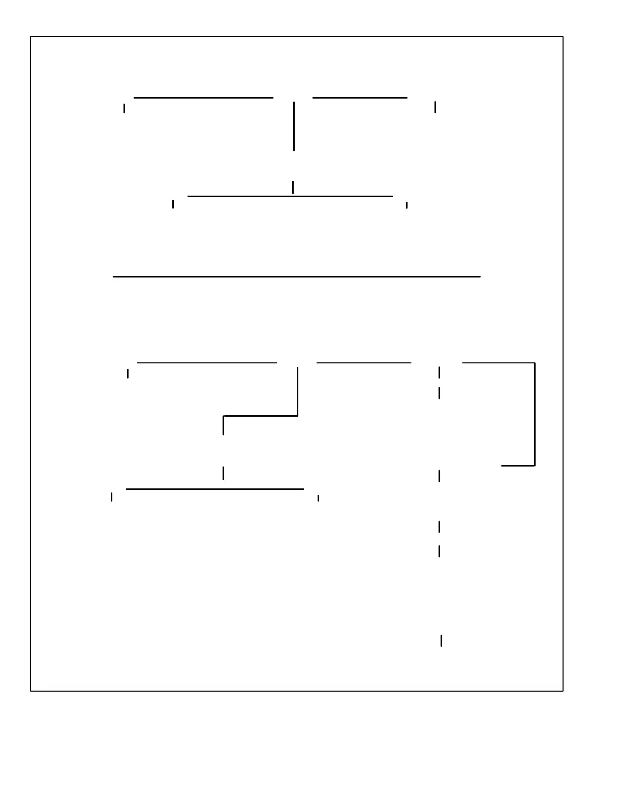
IGNITION CONTROL CHECKOUT GC3
START HERE
FLASHING
IS GREEN DIAGNOSTIC LED LIT?
Turn off unit power at disconnect for at least 3
seconds. Then turn power back on. Allow 3 sec
onds for control to power−up. Control should op
erate properly, proceed to UNIT WILL NOT
RUN"−GAS CHECKS AND SPARK CHECKS to
rule out other possibilities.
If 24 VAC is present between JP72−4 and Common and
LED is not lit, reset power to control. If control still
does not operate, replace control.
NO
LIT
YES
Proceed to
ELECTRICAL CHECKOUT.
Does control A3 have 24VAC
supplied between pins JP72−4
and Common?
Control should operate properly. Pro
ceed to UNIT WILL NOT RUN"−GAS
CHECKS AND SPARK CHECKS to
rule out other possibilities.
NOT LIT
IGNITION CONTROL CHECKOUT G891
START HERE
FLASHING
IS GREEN DIAGNOSTIC LED LIT?
Turn off unit power at disconnect for at least 3
seconds. Then turn power back on. Allow 3 sec
onds for control to power−up. Control should
operate properly, proceed to UNIT WILL NOT
RUN"−GAS CHECKS AND SPARK CHECKS to
rule out other possibilities.
If 24 VAC is present between JP72−4
and Common and LED is not lit, re
set power to control. If control still
does not operate, replace control.
NO
LIT
YES
Proceed to
ELECTRICAL CHECKOUT.
Does control A3 have 24VAC
supplied between pins JP72−4
and Common?
Control should operate properly. Pro
ceed to UNIT WILL NOT RUN"−GAS
CHECKS AND SPARK CHECKS to
rule out other possibilities.
NOT LIT
(0.5 Seconds on, 2.5 seconds off
(0.1 seconds on, 0.1 seconds off)
Check sensor wire for breaks or shorts to
ground and for loose connections to con
trol and/or sensor Check flame signal.
Turn off power
Remove and check sensor
(use 11/16" sensor socket)
1. Was sensor tight when removed?
2. Are cracks present in porcelain?
3. Make ohmmeter check between sensor
termination and center rod. Replace if open.
4. Does the center rod have a coating?
Clean or replace sensor if resistance is above 35 ohms.
Install sensor back in unit. Turn on power. Restart unit.
 Loading...