Page 12
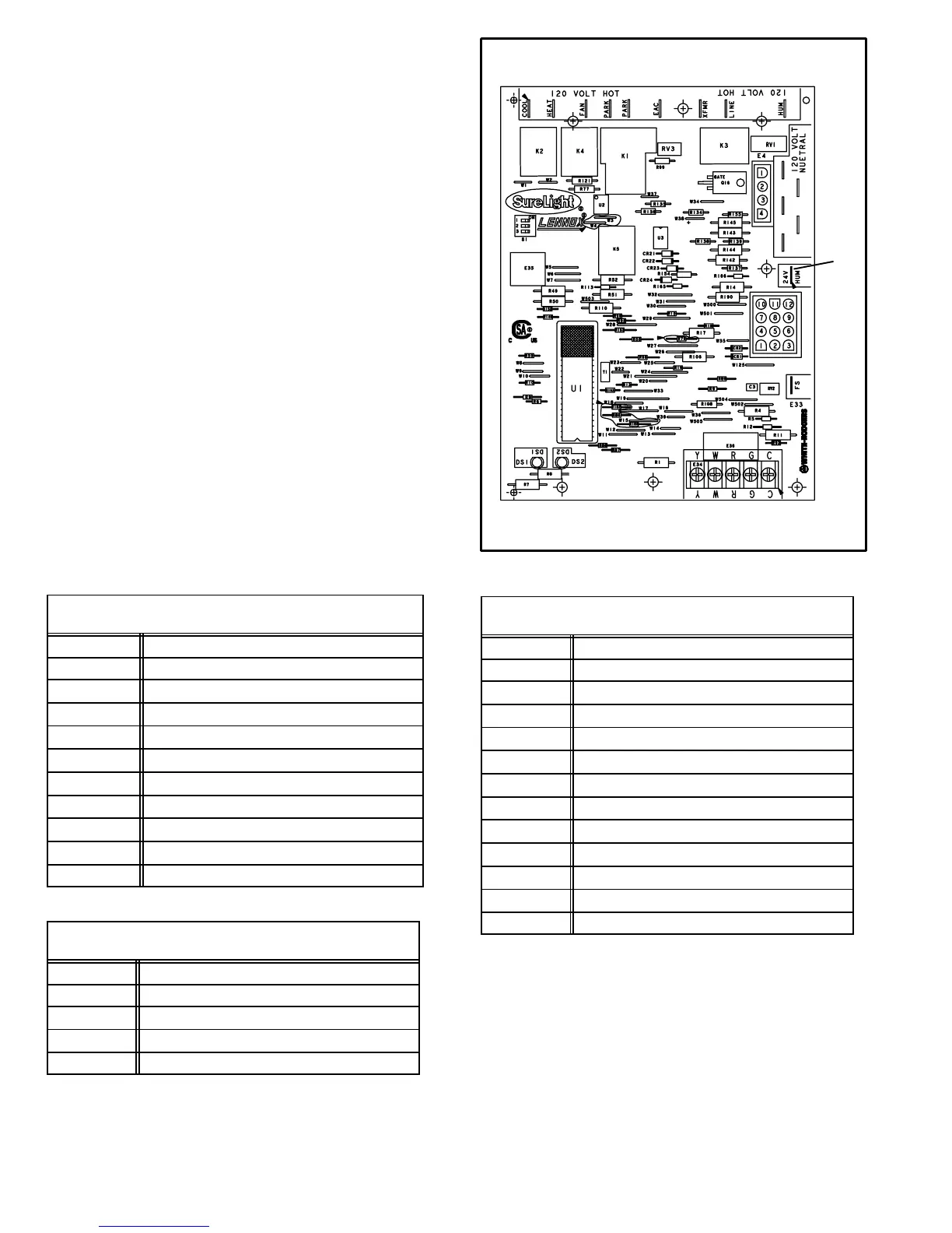
5. SureLight
®
Integrated Ignition Control
69M15 (A92) Figure 8
G51MP045−2, 070−2, 110−2, 135−2, 090−3 and later dash
number units are also equipped with the Lennox SureLight
hot surface ignition system. Like earlier dash number
units, the system consists of ignition control board, ignitor
and sensor. The ignition control and ignitor work in com-
bination to ensure furnace ignition and ignitor durability.
The ignition control controls all major furnace operations.
The ignition control also features two LED lights (DS1 red
and DS2 green) for troubleshooting and two 120 volt ac-
cessory terminals each rated at (1) one amp. A 24 volt ac-
cessory terminal rated at 0.5 amps is also provided. Table 4
shows 24 volt and 120 volt control terminal designations.
Tables 5 and 6 show jack plug terminal designations. See
table 8 for troubleshooting diagnostic codes. Units
equipped with the SureLight hot surface ignition system
can be used with either electronic or electro−mechanical
thermostats without modification. The ignitor is made of
durable silicon−nitride. Ignitor longevity is also enhanced
by voltage ramping by the ignition control. The ignition con-
trol finds the lowest ignitor temperature which will success-
fully light the burner, thus increasing the life of the ignitor.
Each time power is applied to the furnace, the ignition con-
trol performs a self check.
TABLE 4
IGNITION CONTROL 69M15 TERMINAL
DESIGNATIONS
COOL Blower − Cooling Speed (120V)
HEAT Blower − Heating (120V)
PARK
Unused blower lead not energized
FAN
Continuous Low Blower Speed
EAC
Accessory Terminal (120V)
XFMR
Transformer (120V)
LINE
Input (120V)
HUM
Heat Only Accessory (120V)
5 Terminals
120 Volt Neutral
FS
Flame Sensor
24V HUM
Heat Only Accessory (24V)
TABLE 5
IGNITION CONTROL 69M15 (E4) TERMINAL
DESIGNATIONS
PIN # FUNCTION
1 Combustion Air Inducer Line Voltage
2
Ignitor Voltage
3
Combustion Air Inducer Neutral
4
Ignitor Neutral
INTEGRATED IGNITION CONTROL 69M15
FIGURE 8
LED’s
FLAME
TABLE 6
IGNITION CONTROL 69M15 (E1) TERMINAL
DESIGNATIONS
PIN # FUNCTION
1 Prove Switch and Limit Out
2
Not Used
3
24V Hot
4
Not Used
5
Roll Out Switch Out
6
24V Common
7
Limit In
8
Ground
9
Gas Valve Common
10
Prove Switch In
11
Roll Out Switch In
12
Gas Valve 24V Hot
 Loading...