Page 33
4 − Glue the field−provided drain line to the tee. Route the
drain line to an open drain. As an alternate, clear vinyl
tubing may be used to drain condensate away from the
trap. Secure the vinyl tubing to the drain stubs on the
trap using a hose clamp. Do not overtighten the hose
clamp.
Condensate line must be sloped downward away from
condensate trap to drain. If drain level is above con-
densate trap, condensate pump must be used. Con-
densate drain line should be routed within the condi-
tioned space to avoid freezing of condensate and
blockage of drain line. If this is not possible, a heat
cable kit may be used on the condensate trap and line.
Heating cable kit is available from Lennox in various
lengths; 6 ft. (1.8m) − kit no. 26K68; 24 ft. (7.3m) − kit no.
26K69; and 50 ft. (15.2m) − kit no. 26K70.
CAUTION
Do not use copper tubing or existing copper con-
densate lines for drain line.
5 − If unit will be started immediately upon completion of
installation, prime trap per procedure outlined in Unit
Start−Up section.
6 − Glue the provided cap onto the unused condensate
drain line stub.
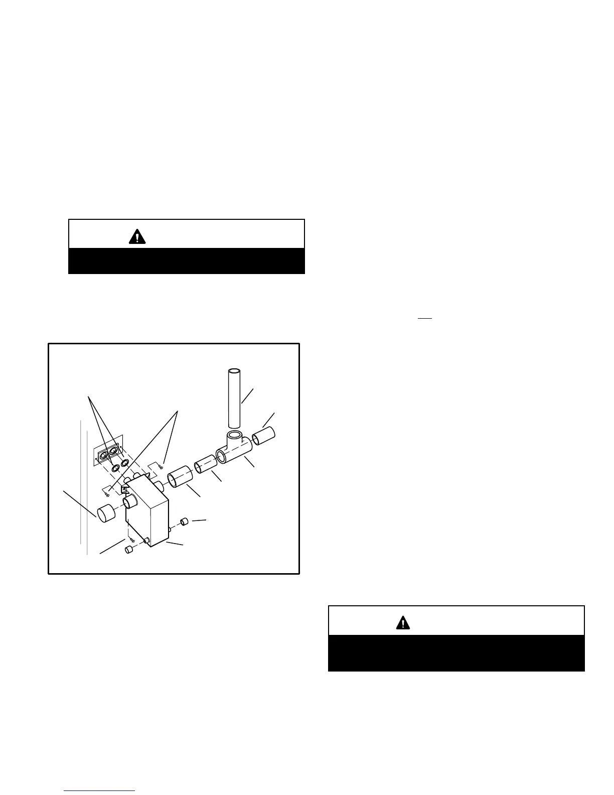
CONDENSATE ASSEMBLY
FIGURE 41
COUPLING
CAP
CONDENSATE TRAP
NIPPLE
NIPPLE
TEE
VENT
CLEAN−OUT ACCESS
(both sides)
HI/LO SCREWS
(DO NOT use power
driver. Hand−tighten
using screw driver.)
SCREW
O−RINGS
III−START-UP
A−Preliminary and Seasonal Checks
1 − Inspect electrical wiring, both field and factory installed for
loose connections. Tighten as required.
2 − Check voltage at disconnect switch. Voltage must be within
range listed on the nameplate. If not, consult the power
company and have voltage condition corrected be-
fore starting unit.
3 − Inspect condition of condensate traps and drain as-
sembly. Disassemble and clean seasonally.
B−Heating Start-Up
BEFORE LIGHTING the unit, smell all around the furnace
area for gas. Be sure to smell next to the floor because
some gas is heavier than air and will settle on the floor.
The gas valve on the G51MP may be equipped with either
a gas control knob or gas control lever. Use only your
hand to push the lever or turn the gas control knob. Never
use tools. If the the lever will not move or the knob will not
push in or turn by hand, replace the valve. Do not try to re-
pair it. Force or attempted repair may result in a fire or ex-
plosion.
Placing the furnace into operation:
G51MP units are equipped with a SureLight
®
hot surface
ignition system. Do not
attempt to manually light burners
on this furnace. Each time the thermostat calls for heat,
the burners will automatically light The ignitor does not
get hot when there is no call for heat on units with Sur-
eLight
®
hot surface ignition system.
Priming Condensate Trap
The condensate trap should be primed with water prior to
start−up to ensure proper condensate drainage. Either
pour 10 fl. oz. (300 ml) of water into the trap, or follow
these steps to prime the trap:
1 − Follow the lighting instructions to place the unit into op-
eration.
2 − Set the thermostat to initiate a heating demand.
3 − Allow the burners to fire for approximately 3 minutes.
4 − Adjust the thermostat to deactivate the heating de-
mand.
5 − Wait for the combustion air inducer to stop. Set the ther-
mostat to initiate a heating demand and again allow the
burners to fire for approximately 3 minutes.
6 − Adjust the thermostat to deactivate the heating demand
and again wait for the combustion air inducer to stop. At
this point, the trap should be primed with sufficient wa-
ter to ensure proper condensate drain operation.
WARNING
If you do not follow these instructions exactly, a fire
or explosion may result causing property damage,
personal injury or death.
Gas Valve Operation
1 − STOP! Read the safety information at the beginning of
this section.
2 − Set the thermostat to the lowest setting.
 Loading...