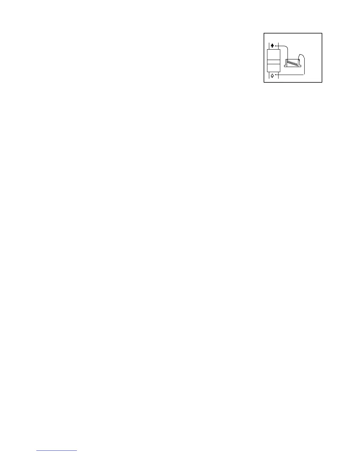
FIGURE 46
STATIC PRESSURE
TEST
G51MP UNIT
Page 38
V−TYPICAL OPERATING CHARACTERISTICS
A−Blower Operation and Adjustment
NOTE− The following is a generalized procedure and
does not apply to all thermostat controls.
1 − Blower operation is dependent on thermostat control
system.
2 − Generally, blower operation is set at thermostat subbase
fan switch. With fan switch in ON position, blower oper-
ates continuously. With fan switch in AUTO position,
blower cycles with demand or runs continuously while
heating or cooling circuit cycles.
3 − In all cases, blower and entire unit will be off when the
system switch is in OFF position.
B−Temperature Rise
Temperature rise for G51MP units depends on unit input,
blower speed, blower horsepower, filter resistance and
installed duct system resistance. The blower speed must be
set for unit operation within the range of AIR TEMP. RISE
°F" listed on the unit rating plate.
To Measure Temperature Rise:
1− Place plenum thermometers in the supply and return air
plenums. Locate supply air thermometer in the first hori-
zontal run of the plenum where it will not pick up radiant
heat from the heat exchanger.
2 − Set thermostat to highest setting.
3 − After plenum thermometers have reached their highest
and steadiest readings, subtract the two readings. The
difference should be in the range listed on the unit rating
plate. If the temperature is too low, decrease blower
speed. If temperature is too high, first check the firing
rate. Provided the firing rate is acceptable, increase
blower speed to reduce temperature. To change blower
speed taps see the Blower Speed Taps section in this
manual.
C−External Static Pressure
1 − Measure tap locations as shown in figure 46.
2 − Punch a 1/4" diameter hole in
supply and return air ple-
nums. Insert manometer
hose flush with inside edge of
hole or insulation. Seal
around the hose with perma-
gum. Connect the zero end of
the manometer to the dis-
charge (supply) side of the system. On ducted systems,
connect the other end of manometer to the return duct
as above. For systems with non−ducted returns, leave
the other end of the manometer open to the atmo-
sphere.
3 − With only the blower motor running and the evaporator
coil dry, observe the manometer reading. Adjust blower
motor speed to deliver the air desired according to the
job requirements.
4 − Static pressure must not exceed 0.5" W.C.
5 − Seal around the hole when the check is complete.
D−Blower Speed Taps
(G51MP−2 & G51MP−090−3 and later units)
Blower speed tap changes are made on the SureLight
®
con-
trol. See figure 8. Unused taps must be secured on dummy
terminals "PARK" on the SureLight board. The heating tap is
connected to the "HEAT " terminal and the cooling tap is con-
nected to the "COOL" terminal. The continuous blower tap is
connected to the "FAN" terminal. To change existing heat tap,
turn off power then switch speed tap on HEAT" terminal with
tap connected to one of two PARK" terminals. See unit wir-
ing diagram for blower speed tap
E−Blower Speed Taps
(All G51MP −1 and G51MP−090−2 units)
Blower speed tap changes are made on the SureLight
®
con-
trol. See figure 6. Unused taps must be secured on dummy
terminals "PARK M1" and or "PARK M2" on the SureLight
board. The heating tap is connected to the "ACB HEAT " ter-
minal and the cooling tap is connected to the "ACB COOL"
terminal. The continuous blower tap is connected to the
"ACB LOW" terminal. To change existing heat tap, turn off
power then switch speed tap on ACB HEAT" terminal with
tap connected to PARK M1" or PARK M2". See unit wiring
diagram for blower speed tap
 Loading...