Page 10
Heat/Cool Equip. Options & Installation
Option 1 − Gas Furnace (with VSM) & Condens-
ing Unit
G32V/G21V/GSR21V Series Gas Furnace
The G32V/G21V (upflow) and the GSR21V (horizontal/re-
verse−flow) are high efficiency gas furnaces that employ a
variable speed blower motor (VSM). The VSM allows the
zone control system to distribute the amount of air that
goes to each zone. These are the only furnaces available
that work with the Harmony
®
II zoning system. See instal-
lation instructions for the G32V, G21V, or GSR21V, which
are provided with the furnace.
Condensing Unit
Any Lennox condensing unit may be used with the Harmo-
ny
®
II zone control system. If a single−speed condensing
unit is used, only two zones are allowed. To reach the full
benefit of the system, a two−speed condensing unit should
be used, which allows up to four zones.
Install the condensing unit as outlined in the installation in-
structions provided with the unit. Install the matching evapora-
tor coil according to the installation instructions furnished with
the coil. The total HVAC system must be properly proportioned
to provide the best comfort.
Option 2 − Blower coil unit (with VSM) & Lennox
Heat Pump
CB31MV Series Blower Coil Unit
The CB31MV (upflow/reverse-flow/horizontal) blower coil
units are equipped with a variable speed blower motor
(VSM) which allows the zoning system to proportion the
amount of air going to each zone. This is the only blower
coil unit that may be used with the Harmony
®
II control sys-
tem. Refer to the CB31MV installation instructions, pro-
vided with the unit, for installation procedures.
Lennox Heat Pump Unit
Any Lennox heat pump unit may be used with the Harmo-
ny
®
II zone control. If a single−speed heat pump is used,
only two zones are allowed. To reach the full benefit of the
zone control system, a two−speed heat pump should be
used, which allows up to four zones.
Install the heat pump as outlined in the installation instruc-
tions provided with the unit. The total HVAC system must be
properly proportioned to provide the best comfort.
Option 3 − Gas Furnace (with VSM) Lennox Heat
Pump, & FM21 Control
G32V/G21V/GSR21V Series Gas Furnace
The G32V/G21V (upflow) and the GSR21V (horizontal/re-
verse−flow) are high efficiency gas furnaces that employ a
variable speed blower motor (VSM) which allows the zone
control system to distribute the amount of air that goes to
each zone. These are the only furnaces available that work
with the Harmony
®
II zoning system. See the installation
instructions for the G32V, G21V, or GSR21V which are pro-
vided with the furnace.
Lennox Heat Pump Unit
Any Lennox heat pump unit may be used with the Harmo-
ny
®
II zone control system. If a single−speed heat pump is
used, only two zones are allowed. To reach the full benefit
of the system, a two−speed heat pump should be used,
which allows up to four zones.
Install the heat pump as outlined in the installation instruc-
tions provided with the unit. The total HVAC system must be
properly proportioned to provide the best comfort.
Lennox FM21 Control
The FM21 control coordinates the operation of any Lennox
heat pump and a G32V, G21V, or GSR21V furnace to supply
the different stages of heat. Two optional kits are available for
use with the FM21: the SLC1−service light kit and the
DTR1−defrost kit. Refer to the FM21, SLC1, and/or DTR1 in-
structions for installation and operation sequences.
Component Selection & Installation
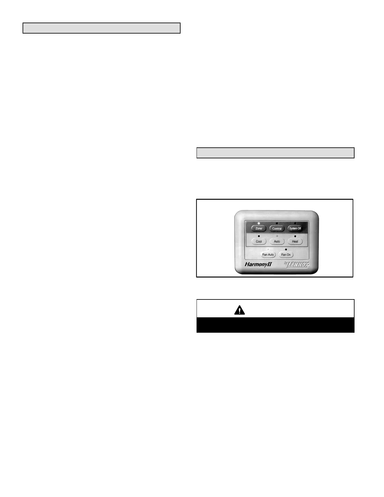
A − Control Panel
Install the Harmony
®
II control panel so that it is accessible to
the user. Typically, locate the control panel near the zone 1
master thermostat.
Harmony
®
II Control Panel
Figure 5
CAUTION
Do not damage the PC board as you install the con-
trol panel.
1− Remove the cover of the control panel by holding the
base section and gently pulling the cover out at the bot-
tom. Pivot the cover up and lift it away from the base.
2− Drill two holes to accommodate the anchors that will
hold the control panel. Use a saw or sheetrock knife to
cut out a rectangular section of the wall. You will run the
thermostat cable from the control center to the control
panel through this section.
3− Insert two plastic anchors into the wall.
4− Attach a six−wire thermostat cable to the terminal block
which is located on the back of the system control pan-
el. Identify and mark each of the six wires (1, 2, 3, 4,
5, and 6) for wiring to the zone control center.
5− Using the provided screws, position the mounting base
and secure it to the wall. Route the thermostat wires
through the opening in the middle of the mounting base.
 Loading...

