Page 19
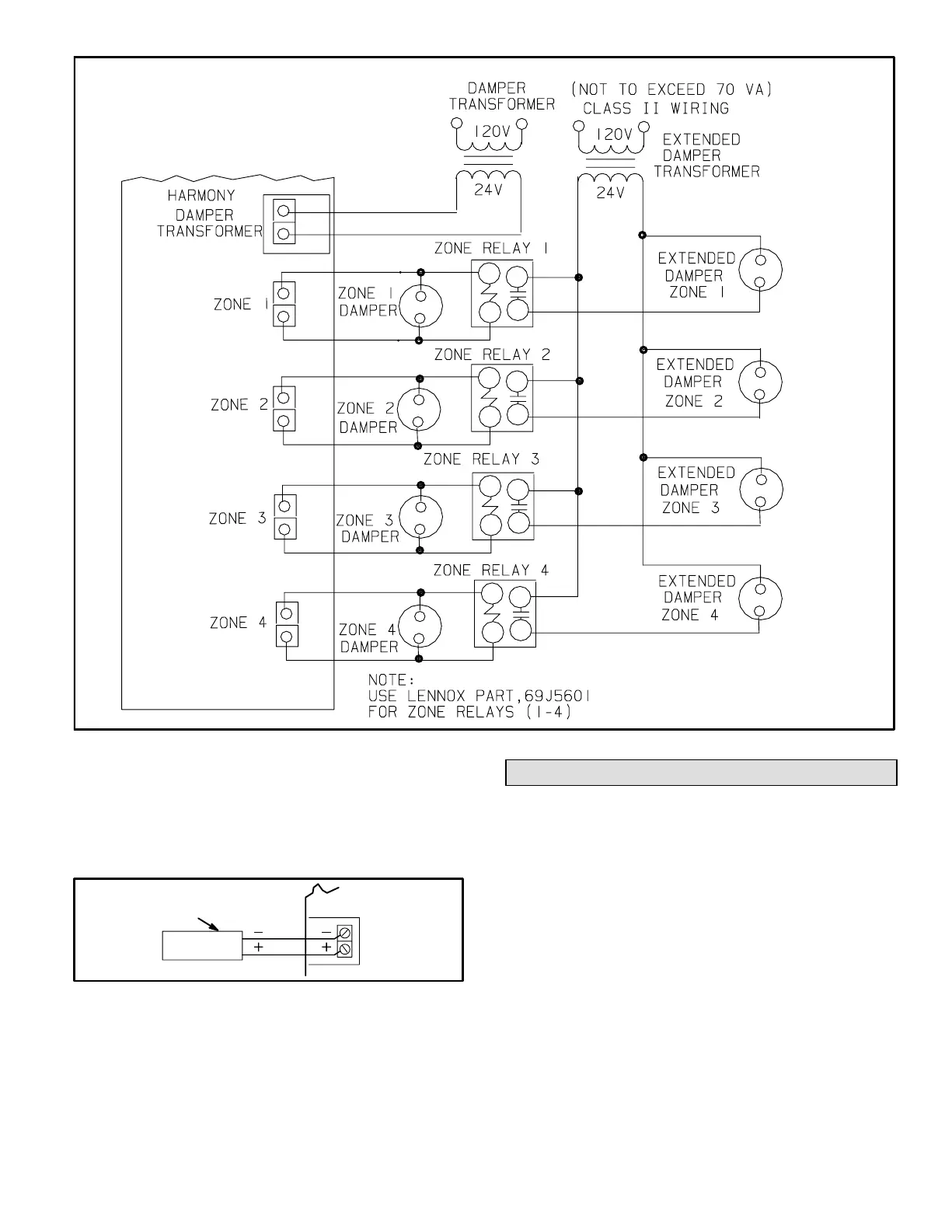
Figure 19
TRANSFORMER RATING SHOULD BE SIZED TO ADE-
QUATELY HANDLE ZONE DAMPERS (1−4) PLUS RELAYS
(K1−K4) NOT TO EXCEED CLASS II WIRING LIMIT OF 70
VA.
COMBINED LOAD OF ZONE DAMERS AND ZONE RE-
LAYS NOT TO EXCEED 2 AMPS.
Discharge Air Temperature Probe Wiring
Wire discharge air temperature probe to control center us-
ing thermostat wire. Red wire is connected to the positive
(+) terminal and black wire is connected to the negative (−)
terminal. See figure 20.
Figure 20
DISCHARGE
TEMPERATURE
PROBE
CONTROL
CENTER
DISCHARGE
PROBE
Component Specific Wiring
THERMOSTAT WIRING
Option 1 − G32V/G21V/GSR21V Series Gas Furnace
& Condensing Unit
1. Wire each thermostat with four−wire thermostat cable
to terminals Y, W, R, and C.
2. Run thermostat cable from each of the thermostats to
the control center. Mark each cable according to the
zone thermostat that it is from.
3. Strip the cables and attach each of the three wires to
the control center as shown in figure 23.
4. Set heat anticipator of each thermostat to 0.10 .
 Loading...

