Page 2
Introduction
The Lennox Harmony
®
II Zone Control System manages the
distribution of conditioned air to specific areas or zones in a
house or small commercial building.
The zone control system allows the user to heat or cool occu-
pied areas without conditioning unused areas, which may re-
sult in lower utility bills. This control orchestrates the system
components to provide a balanced and comfortable environ-
ment.
The Harmony
®
II zone control system operates with any of the
following HVAC system combinations:
Option 1 − G32V/G21V/GSR21V series furnace and either
a single− or two− speed condensing unit
Option 2 − CB31MV series blower coil unit and either a Len-
nox single− or two− speed heat pump or air conditioner.
Option 3 − G32V/G21V/GSR21V series furnace, a Lennox
heat pump, and the FM21 control
The Harmony
®
II zone control system uses off−the−shelf
thermostats and dampers with any of the above options to
distribute conditioned air to different zones. Without this
control, a homeowner would have to purchase multiple
HVAC systems to condition different areas of a residence.
The zone control system operates in two modes: Central
Control mode or Zone Control mode. Based upon a de-
mand from the master thermostat, the Central Control mode
allows the heating and cooling system to condition all of the
zones. When the zone control system is in the Zone Control
mode, a zone is conditioned only upon demand. The Har-
mony
®
II control panel uses light emitting diodes (LEDs) to
indicate the current operating mode.
The zone control system is easy to install. The wiring to the
control center is all low voltage; therefore, use ordinary 18
AWG thermostat wire. The zone control system is ideal for
retrofit as well as new construction. The zone control sys-
tem controls the air volume of the blower, which eliminates
the need for bypass dampers and discharge temperature
limit switches.
Operating the zone control system is simple. The user oper-
ates the system with the control panel and the zone thermo-
stats. The Harmony
®
II control panel does not require pro-
gramming. However, a programmable thermostat is
available which allows the user to choose a specialized heat-
ing and cooling sequence. While in zone mode, a standard
thermostat controls the temperature for its particular zone.
There is no over−riding or reprogramming to condition the
zone.
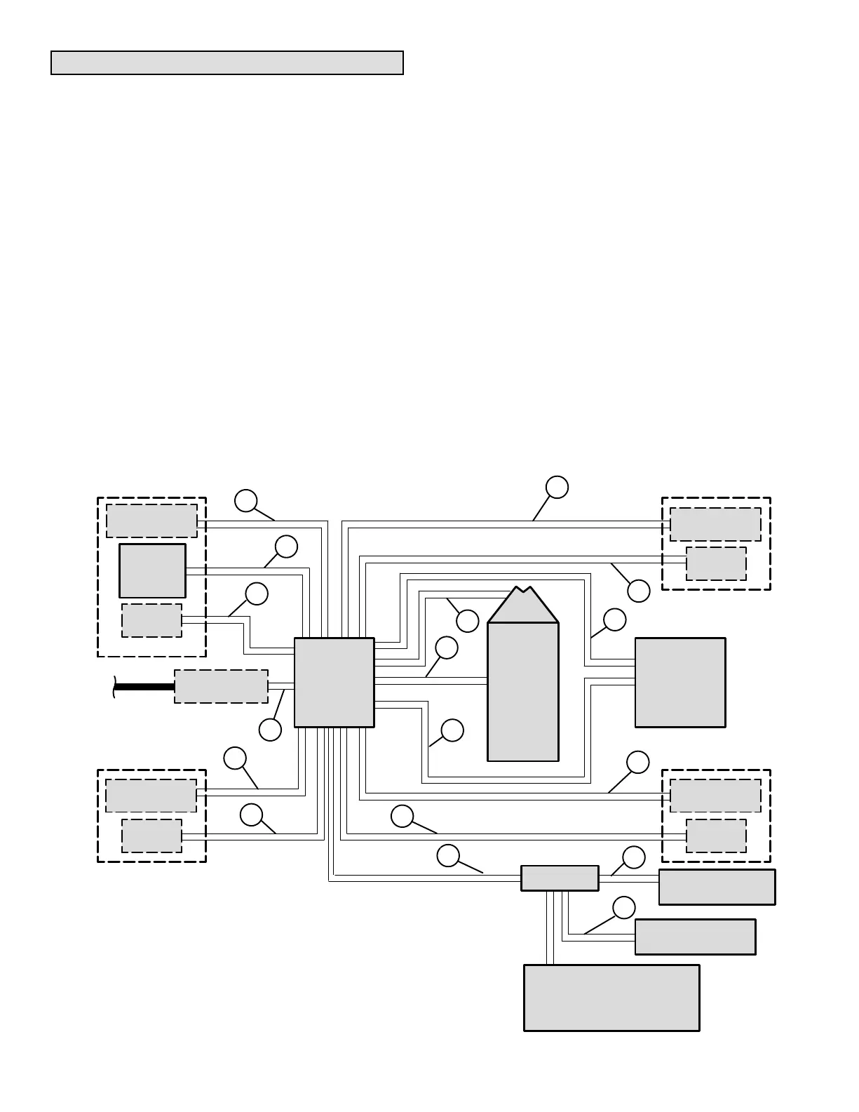
Harmony
®
II Residential Zone Control System − Field Wiring
COIL
ZONE
SYSTEM
CONTROL
PANEL
ZONE
DAMPER
G21V /
GSR21V
FURNACE
OR
CB31MV
BLOWER
COIL UNIT
ZONE 1 ZONE 2
*ZONE 3
*ZONE 4
POWER
* NOTE Zone 3 and Zone 4 Not Available
With Single Speed Outdoor Unit.
THERMOSTAT
(MASTER)
ZONE
SYSTEM
CONTROL
CENTER
ZONE
DAMPER
THERMOSTAT
(ZONE)
CONDENSING
UNIT
OR
HEAT PUMP
OUTDOOR
UNIT
ZONE
DAMPER
ZONE
DAMPER
A
A
A
A
B
B
B
B
C
D
G
B
ZONE DAMPER
TRANSFORMER
THERMOSTAT
(ZONE)
THERMOSTAT
(ZONE)
E
F
FM21
PLENUM MOUNTED
DISCHARGE PROBE
H
I
J
FUEL MASTER
1ST STAGE HP =10 WIRE
2ND STAGE HP = 12 WIRE
OUTDOOR
THERMOSTAT
A − Three wire low voltage (gas heat systems) 18 ga. minimum
Five wire low voltage (heat pump systems) 18 ga. minimum
B − Two wire low voltage 18 ga. minimum
C − Seven wire low voltage 18 ga. minimum
D − Six wire low voltage 18 ga. minimum
E − Two wire low voltage (single speed condensing unit) 18 ga. minimum
Three wire low voltage (two speed condensing unit) 18 ga. minimum
Four wire low voltage (single speed heat pump outdoor unit) 18 ga. minimum
Five wire low voltage (two speed heat pump outdoor unit) 18 ga. minimum
F − Two wire low voltage (discharge air sensor) 18 ga. minimum
G − Two wire low voltage pressure switch (heat pump only) 18 ga. minimum
H − Eight wire 18 ga. minimum
I − Three wire 18 ga. minimum
J − Two wire 18 ga. minimum
 Loading...

