- 3 -
1. Smart Hub
1.1. Installation
DO NOT install the Smart Hub on indoor unit, duct work or any equipment that could induce vibration.
Mount Smart Hub on flat surface away from indoor unit to minimize vibration. Securing module to a wall stud is desir
able. If mounted on metal surface other than above, antennas need to be perpendicular to the metal surface.
1.2. Antennas
Unfold both antennas to the vertical position. Adjustments may be required to optimized transmitting and receiving.
1.3. Wire Connections
1.3.1. Wire gauge and Maximum Run Length:
The Smart Hub connects to the indoor unit through common four-conductor thermostat wire. It receives 24VAC
power from the indoor unit over two wires and communicates with the indoor unit and the rest of the HVAC
system through two different wires. Wiring from the Smart Hub to the indoor unit should be limited to 300 feet or
less (for 18 AWG wire).
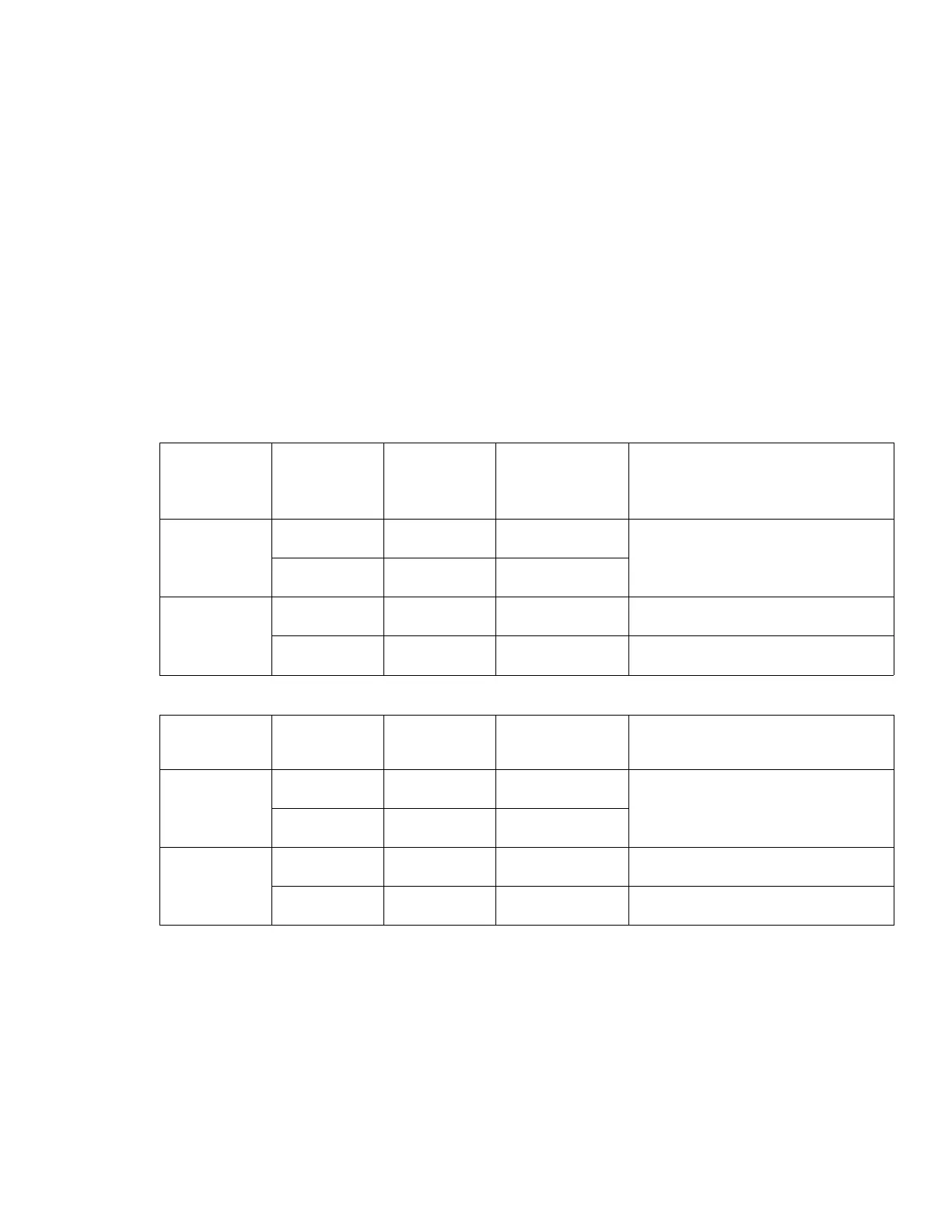
1.3.2. Smart Hub to Mag-Mount Terminal Connections
Type
Smart Hub
Terminal
Labels
Mag-Mount
Terminal
Labels
Terminal Color Function
RS-485
+ + Yellow
Two wire serial RS-485 interface,
3.3V signaling up to 400 feet.
- - Green
24VAC
Power
A A Blue 24VAC RS-bus power input
B
B
Black 24VAC RS-bus common input
1.3.3. Smart Hub to Indoor Unit Terminal Connections
Type
Smart Hub
Terminal
Labels
Indoor Unit
Terminal
Labels
Terminal Color Function
RS-BUS
I+ I+ Yellow
RS-bus high – data line 1
RS-bus high – data line 2
i- i- Green
24VAC
Power
R R Red 24VAC RS-bus power input
C
C
Black 24VAC RS-bus common input

 Loading...