Page 28
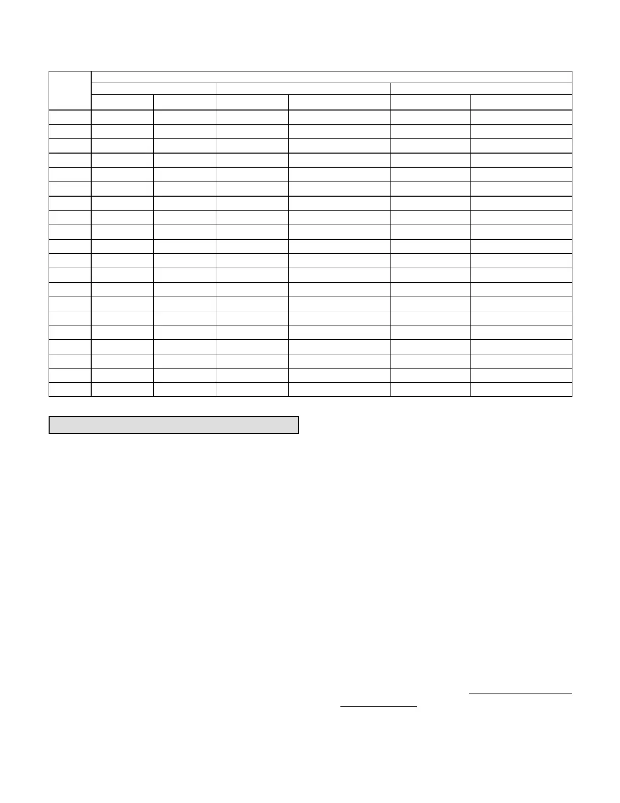
LGH/LCH036, 048, 060, 072
TABLE 6
MANUFACTURER'S DRIVE COMPONENT NUMBERS
Drive No.
DRIVE COMPONENTS
Motor Pulley Blower Pulley bELT
Supplier No. OEM Part No. Supplier No. OEM Part No. Supplier No. OEM Part No.
A01 1VP34x7/8 31K6901 AK54 x 1 100244-19 A40 100245-17
A02 1VP34x7/8 31K6901 AK49 x 1 100244-18 A39 100245-16
A03 1VP34x7/8 31K6901 AK44 x 1 100244-16 A39 100245-16
A05 1VP34x7/8 31K6901 AK41 x 1 100244-15 A39 100245-16
A06 1VP44x7/8 P-8-1488 AK51 x 1 18L2201 A41 100245-18
A07 1VP50x7/8 P-8-2187 AK54 x 1 100244-19 AX43 73K8201
AA01 1VP34x7/8 31K6901 AK69 x 1 37L4701 AX51 13H0101
AA02 1VP40x7/8 79J0301 BK80H
1
100788-03 A53 P-8-4951
AA03 1VP40x7/8 79J0301 AK59 x 1 31K6801 A50 100245-29
AA04 1VP44x7/8 P-8-1488 AK59 x 1 31K6801 AX51 13H0101
A01T
2
1VP34x7/8 31K6901 AK54 x 1 100244-19 A41 100245-18
A02T
2
1VP34x7/8 31K6901 AK49 x 1 100244-18 A40 100245-17
A03T
2
1VP34x7/8 31K6901 AK44 x 1 100244-16 A40 100245-17
A05T
2
1VP34x7/8 31K6901 AK41 x 1 100244-15 A41 100245-18
A06T
2
1VP44x7/8 P-8-1488 AK51 x 1 18L2201 A41 100245-18
A07T
2
1VP50x7/8 P-8-2187 AK54 x 1 100244-19 AX43 73K8201
AA01T
2
1VP34x7/8 31K6901 AK69 x 1 37L4701 A50 100245-29
AA02T
2
1VP40x7/8 79J0301 BK80H* 100788-03 A52 100245-30
AA03T
2
1VP40x7/8 79J0301 AK59 x 1 31K6801 A49 100245-32
AA04T
2
1VP44x7/8 P-8-1488 AK59 x 1 31K6801 A50 100245-29
NOTES:
1
Requires split taper bushing, Browning no. H1; OEM no. 100073-04
2
Includes tension assembly, Fenner no. FS0590; OEM no. 101994-02
Cooling Start-Up
A-Operation
1- Initiate first and second stage cooling demands
according to instructions provided with Unit
Controller Installation and Setup Guide. Use the
menu navigation arrows and select button; see
Service - Test.
2- No Economizer Installed in Unit -
A first-stage cooling demand (Y1) will energize the
compressor and blower in low speed along with the
condenser fan. An increased cooling demand (Y2)
will increase the blower and compressor to high
speed.
Units Equipped With Economizer -
When outdoor air is acceptable, a first-stage
cooling demand (Y1) will energize the economizer.
An increased cooling demand (Y2) will energize
the compressor and low speed blower along with
the condenser fan. When outdoor air is not
acceptable unit will operate as though no
economizer is installed.
3- Units contain one refrigerant circuit or stage.
4- Unit is charged with R-410A refrigerant. See unit
rating plate for correct amount of charge.
5- Refer to Cooling Operation and Adjustment section for
proper method to check refrigerant charge.
B-Three Phase Scroll Compressor Voltage Phasing
Three phase scroll compressors must be phased
sequentially to ensure correct compressor and blower
rotation and operation. Compressor and blower are
wired in phase at the factory. Power wires are
color-coded as follows: line 1-red, line 2-yellow, line
3-blue.
1- Observe suction and discharge pressures and
blower rotation on unit start-up.
2- Suction pressure must drop, discharge pressure
must rise, and blower rotation must match rotation
marking.
If pressure differential is not observed or blower rotation is
not correct:
3- Disconnect all remote electrical power supplies.
4- Reverse any two field-installed wires connected to
the line side of K1 contactor. Do not reverse wires at
blower contactor.
5- Make sure the connections are tight.
Discharge and suction pressures should operate at
their normal start‐up ranges.

 Loading...
