Page 6
LGH/LCH036, 048, 060, 072
LG
LC
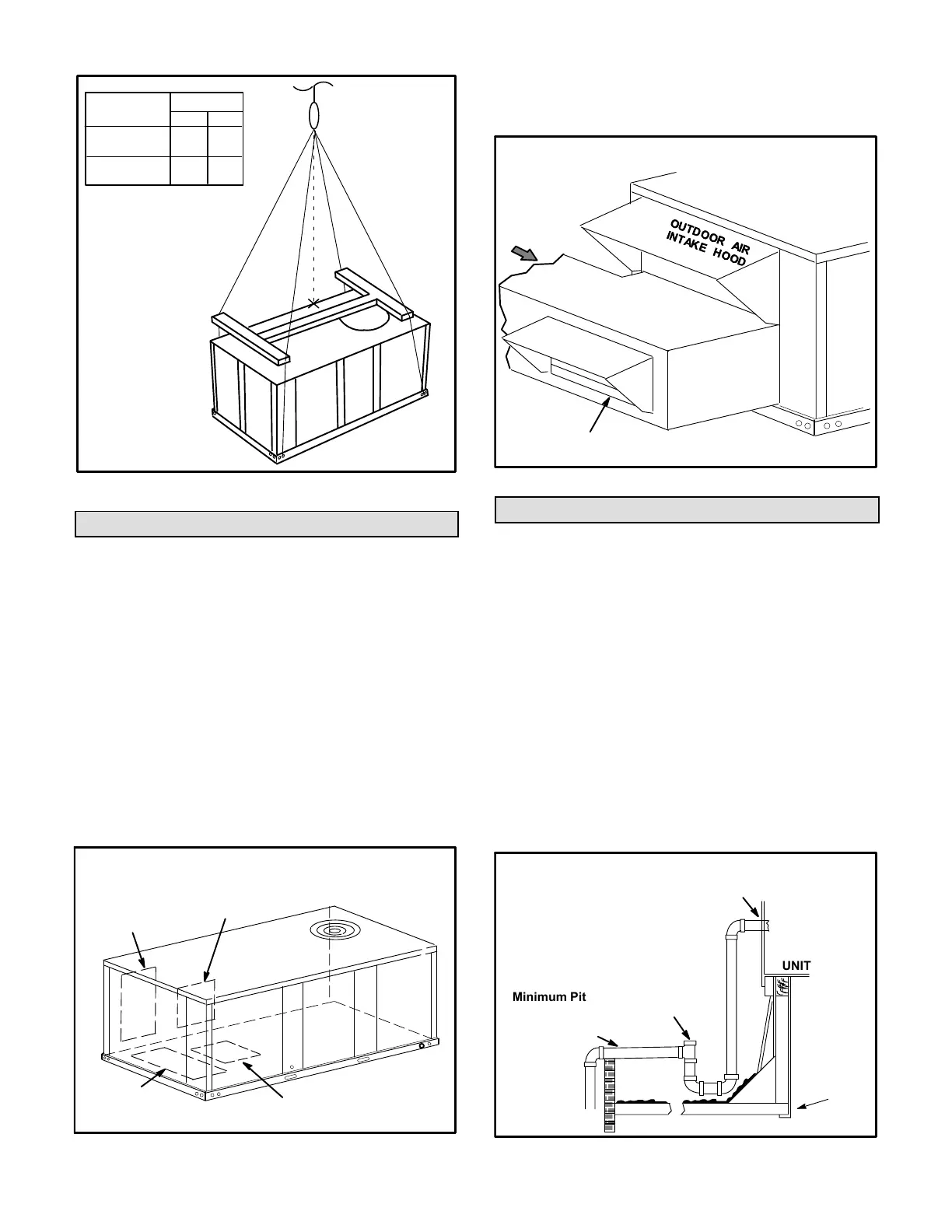
FIGURE 2
IMPORTANT - ALL
PANELS MUST
BE IN PLACE
FOR RIGGING.
LIFTING POINT SHOULD
BE DIRECTLY ABOVE
CENTER OF GRAVITY
*Maximum weight with all available
factory-installed accessories.
435
423
Unit
*Weight
Lbs. Kg.
CAUTION - Do
not walk on unit.
960
933
Horizontal Air Discharge
Unit is shipped with panels covering the horizontal supply
and return air openings. Remove horizontal covers and
place over downflow openings for horizontal air discharge.
See figure 3. Secure in place with sheet metal screws.
Units Equipped With An Optional Economizer
1- Remove the horizontal supply air cover and position
over the downflow supply air opening. Secure with
sheet metal screws.
2- Leave the horizontal return air cover in place.
3- Locate the separately ordered horizontal air
discharge kit. Place the kit panel over the downflow
return air opening.
4- Remove and retain the barometric relief dampers and
lower hood.
FIGURE 3
DOWNFLOW
RETURN AIR
OPENING
UNIT SUPPLY AND RETURN AIR OPENINGS
DOWNFLOW
SUPPLY AIR
OPENING
HORIZONTAL
RETURN AIR
OPENING
HORIZONTAL
SUPPLY AIR
OPENING
5- Install return air duct beneath outdoor air intake. See
figure 4. Install barometric relief damper in lower
hood and install in ductwork as shown in figure 4.
FIGURE 4
HORIZONTAL RETURN AIR DUCTWORK
WITH ECONOMIZER
HORIZONTAL
RETURN AIR
DUCT
INSTALL BAROMETRIC RELIEF DAMPERS
AND HOOD IN RETURN AIR DUCT
UNITUNIT
Condensate Drains
Make drain connection to the drain coupling provided on
unit. Older model units have a 3/4” N.P.T. coupling and
newer model units have a 1” N.P.T. coupling.
Note - The drain pan is made with a glass reinforced
engineered plastic capable of withstanding typical joint
torque but can be damaged with excessive force. Tighten
pipe nipple hand tight and turn an additional quarter turn.
A trap must be installed between drain connection and an
open vent for proper condensate removal. See figure 5 or
6. It is sometimes acceptable to drain condensate onto
the roof or grade; however, a tee should be fitted to the
trap to direct condensate downward. The condensate line
must be vented. Check local codes concerning
condensate disposal. Refer to pages 1 and 2 for
condensate drain location.
FIGURE 5
UNIT
Minimum Pitch
1” (25 mm) per
10' (3 m) of line
MOUNTING
FRAME
OPEN VENT
CONDENSATE SIDE DRAIN CONNECTION
NOTE - Allow clearance to
open doors when installing
condensate piping.
CAULK AROUND CONDENSATE COUPLING

 Loading...
