Page 30
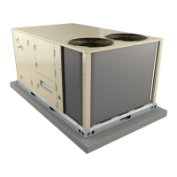
SIEMENS OVERLOAD RELAY
Adjust relay amp setting according to value given on the blower motor nameplate. Proper relay amp
setting equals motor nameplate FLA X service factor of 1.15 X .95.
Use small slotted screwdriver to adjust control mode from automatic reset (A) to manual reset (H).
Control must be in the manual reset mode (H) to perform a test. Press the red test button. Green trip
indicator should pop out. Press the blue reset screw to reset the relay.
BLUE RESET BUTTON IN
FACTORY‐SET AUTO MODE
(Turn clockwise to H for
manual reset)
GREEN TRIP INDICATOR
(Flush with surface -- not tripped;
Above surface -- tripped)
AMP ADJUSTMENT DIAL
RED TEST BUTTON
FIGURE 10
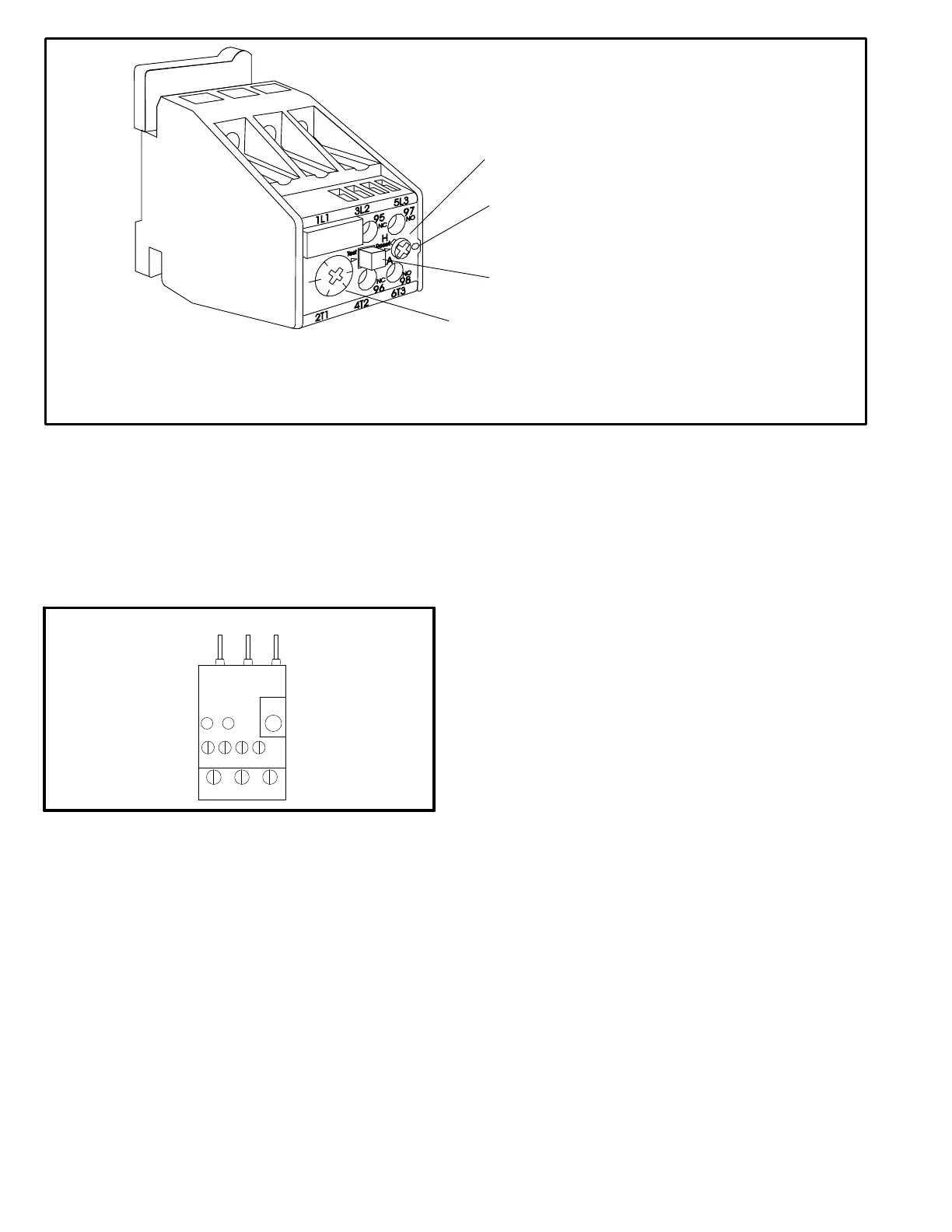
13-Compressor Overload Relays S176, S177
(M-volt CE units)
Relays are wired in series with the appropriate compres
sor contactor and monitor the current flow to the compres
sor motor. When the relay senses an overload condition,
N.C. contacts open to de-energize the compressor. Re
lays are manufactured by Siemens; see figure 11.
FIGURE 11
COMPRESSOR OVERLOAD RELAYS
SET RELAYS
TO MAXIMUM
OVERLOAD
SETTING
14-Variable Frequency Drive A96 (optional)
Units may be equipped with a VFD which alters the supply
power frequency and voltage to the blower motor. Blower
speed is staged depending on the compressor stages,
heating demand, ventilation demand, or smoke alarm.
The amount of airflow for each stage is preset from the fac
tory. Airflow can be adjusted as shown in Belt Drive Supply
Air Inverter section. The VFD is located below the Unit
Controller.
15-VFD Power To Motor Contactor K202
(optional)
Contactor is used in VFD units equipped with a VFD bypass
option. The three‐pole contactor with a 24VAC coil is ener
gized by the A55 Unit Controller. K202 allows power from the
VFD to the B3 blower motor in response to blower demand.
16-Inverter Start Forward Rotation Relay K203
(optional)
Relay is used in optional VFD units and is a three-pole dou
ble-throw relay with a 24VAC coil. K203 is energized by the
A55 Unit Controller and provides input to the A96 VFD to
start blower forward rotation. K203 also de-energizes K3
allowing A96 to control B3 blower.
17-VFD Controller (GP board) A133 (VFD
units)
M2 and earlier versions of Unit Controller only. The GP
board A133 controls and monitors the status of the VFD
A96. The board sends the signal to start the VFD forward
rotation and also sends a 0-10VDC signal to the VFD to
control the speed of the blower rotation. A133 also reports
VFD malfunctions to the A55.
 Loading...