Page 66
L14 Reheat Coil Solenoid Valve
When Unit Controller input (Unit Controller J298-5 or
J299-8) indicates room conditions require dehumidifi
cation, L14 reheat valve is energized (Unit Controller
P269-3) and refrigerant is routed to the reheat coil.
Reheat Setpoint
Reheat is factory-set to energize when indoor relative hu
midity rises above 60% (default). The reheat setpoint can
be adjusted by changing Unit Controller Settings - Control
menu. A setting of 100% will operate reheat from an energy
management system digital output. The reheat setpoint
can also be adjusted using an optional Network Control
Panel (NCP).
Reheat will terminate when the indoor relative humidity falls
3% (57% default) or the digital output de-energizes. The re
heat deadband can be adjusted at Settings - Control menu.
Check-Out
Test Hot Gas Reheat operation using the following proce
dure.
1- Make sure reheat is wired as shown in wiring section.
2- Make sure unit is in local thermostat mode.
3- Select Unit Controller Service - Test.
The blower and compressor 1 (reheat) should be operating.
Reheat mode will be appear on the Unit Controller display.
4- Deselect Unit Controller Service - Test.
Compressor 1 (reheat) and blower should de-energize.
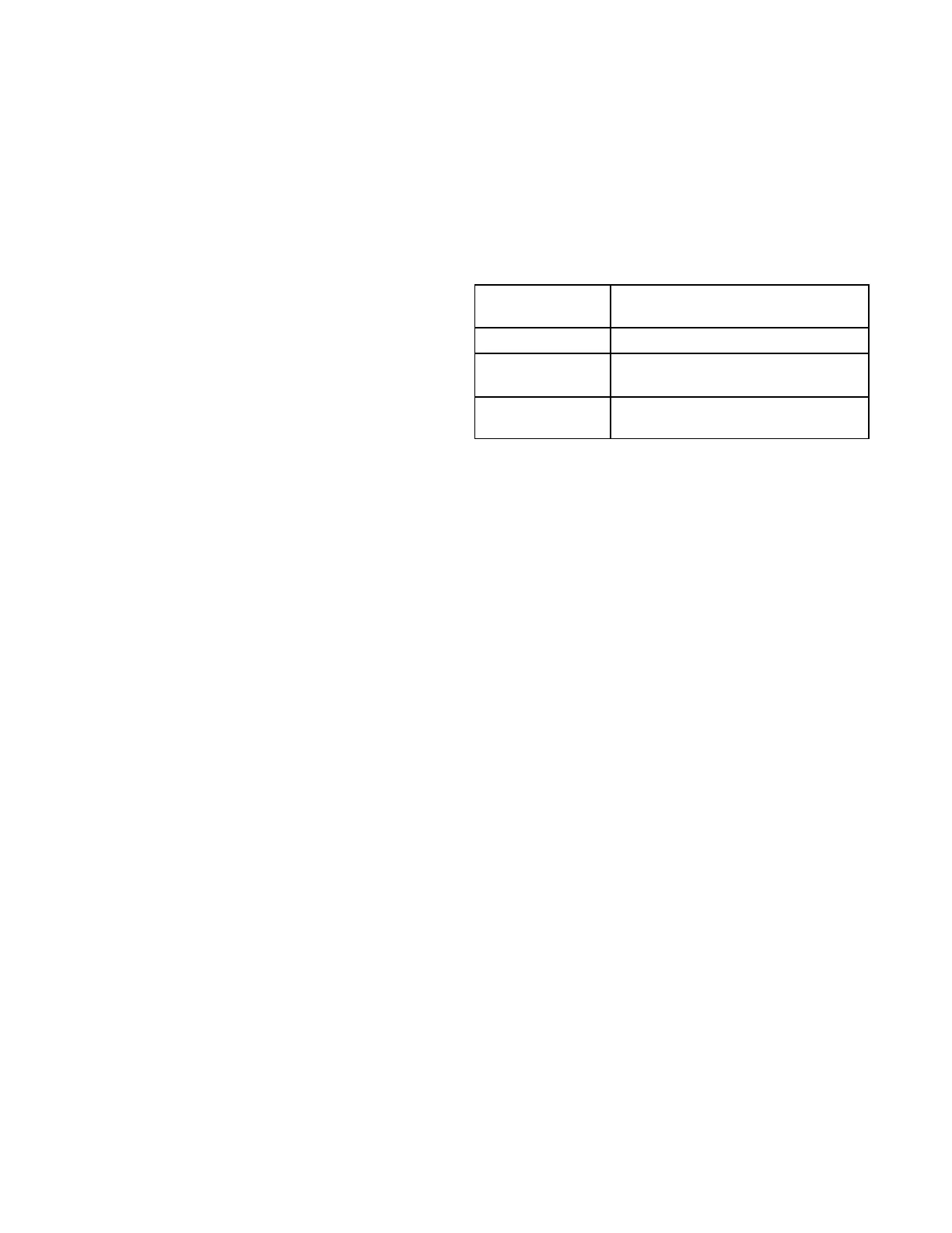
Default Reheat Operation
TABLE 25
Reheat Operation - Two Cooling Stages - Default
T'stat and Hu
midity Demands
Operation
Reheat Only Compressor 1 Reheat
Reheat & Y1
Compressor 1 Reheat &
Compressor 2 Cooling*
Reheat & Y1 & Y2
Compressor 1 Cooling &
Compressor 2 Cooling**
*If there is no reheat demand and outdoor air is suitable,
free cooling will operate.
**If there is no reheat demand and outdoor air is suitable,
free cooling and compressor 1 will operate.
 Loading...